Product Description
Basic Info
|
ANSI NO: |
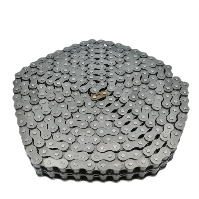
100-2R |
DIN/ISO NO: |
20A-2 |
|
Pitch (mm): |
31.75 |
Roller Diameter(mm): |
19.05 |
|
Pin Diameter(mm): |
9.53 |
Plate Thickness (mm): |
4.00 |
|
Inner Plate Width (mm): |
18.90 |
Average Tensile Strength: |
215.2KN |
|
Chain Size: |
5FT, 10FT, 5Meters |
Weight / Meter (kgs/m): |
3.91 |
|
Origin: |
HangZhou China |
HS Code: |
7315119000 |
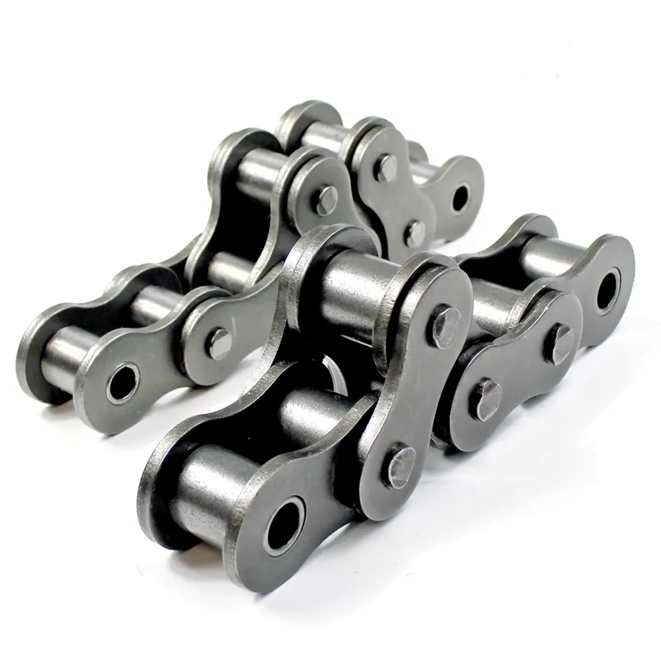
SMCC roller chain is 1 of the most widely used and welcome products in the market. Its continuous innovative development is suitable to be the solutions for many conditions, standard roller chains, motorcycle driving chain, O-ring motorcycle chain, high strength roller chain, conveyor chains, agricultural driving chain, galvanized chain, nickel-plated chain, lubrication-free chain and oilfield chain etc
Our CHINAMFG chain was produced by machinery processing from raw materials to finished products and a full set of quality testing equipment. Mechanical processing equipment include grinding machines, high speed punching machines, milling machines, high speed automatic rolling and assembling machine. Heat treatment was processed by continuous mesh belt conveyor furnace, mesh belt conveyor annealing furnace, advanced central control system of heat treatment, rotary CHINAMFG for chain component heat treatment, which ensure the stability and consistency of the key function of chain components.
We are the best suppliers of Chinese largest palletizing robot enterprises. These items are durable quality with affordable prices, replace of Japan chains, ZheJiang chains exported to Europe, America, Asia and other countries and regions.
Workshop Show
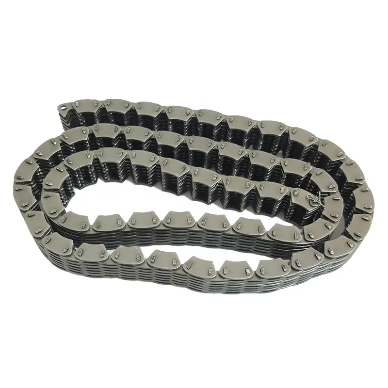
ROLLER CHAIN
Roller chain or bush roller chain is the type of chain drive most commonly used for transmission of mechanical power on many kinds of domestic, industrial and agricultural machinery, including conveyors, wire- and tube-drawing machines, printing presses, cars, motorcycles, and bicycles. It consists of a series of short cylindrical rollers held together by side links. It is driven by a toothed wheel called a sprocket. It is a simple, reliable, and efficient means of power transmission.
CONSTRUCTION OF THE CHAIN
Two different sizes of roller chain, showing construction.
There are 2 types of links alternating in the bush roller chain. The first type is inner links, having 2 inner plates held together by 2 sleeves or bushings CHINAMFG which rotate 2 rollers. Inner links alternate with the second type, the outer links, consisting of 2 outer plates held together by pins passing through the bushings of the inner links. The “bushingless” roller chain is similar in operation though not in construction; instead of separate bushings or sleeves holding the inner plates together, the plate has a tube stamped into it protruding from the hole which serves the same purpose. This has the advantage of removing 1 step in assembly of the chain.
The roller chain design reduces friction compared to simpler designs, resulting in higher efficiency and less wear. The original power transmission chain varieties lacked rollers and bushings, with both the inner and outer plates held by pins which directly contacted the sprocket teeth; however this configuration exhibited extremely rapid wear of both the sprocket teeth, and the plates where they pivoted on the pins. This problem was partially solved by the development of bushed chains, with the pins holding the outer plates passing through bushings or sleeves connecting the inner plates. This distributed the wear over a greater area; however the teeth of the sprockets still wore more rapidly than is desirable, from the sliding friction against the bushings. The addition of rollers surrounding the bushing sleeves of the chain and provided rolling contact with the teeth of the sprockets resulting in excellent resistance to wear of both sprockets and chain as well. There is even very low friction, as long as the chain is sufficiently lubricated. Continuous, clean, lubrication of roller chains is of primary importance for efficient operation as well as correct tensioning.
LUBRICATION
Many driving chains (for example, in factory equipment, or driving a camshaft inside an internal combustion engine) operate in clean environments, and thus the wearing surfaces (that is, the pins and bushings) are safe from precipitation and airborne grit, many even in a sealed environment such as an oil bath. Some roller chains are designed to have o-rings built into the space between the outside link plate and the inside roller link plates. Chain manufacturers began to include this feature in 1971 after the application was invented by Joseph Montano while working for Whitney Chain of Hartford, Connecticut. O-rings were included as a way to improve lubrication to the links of power transmission chains, a service that is vitally important to extending their working life. These rubber fixtures form a barrier that holds factory applied lubricating grease inside the pin and bushing wear areas. Further, the rubber o-rings prevent dirt and other contaminants from entering inside the chain linkages, where such particles would otherwise cause significant wear.[citation needed]
There are also many chains that have to operate in dirty conditions, and for size or operational reasons cannot be sealed. Examples include chains on farm equipment, bicycles, and chain saws. These chains will necessarily have relatively high rates of wear, particularly when the operators are prepared to accept more friction, less efficiency, more noise and more frequent replacement as they neglect lubrication and adjustment.
Many oil-based lubricants attract dirt and other particles, eventually forming an CHINAMFG paste that will compound wear on chains. This problem can be circumvented by use of a “dry” PTFE spray, which forms a solid film after application and repels both particles and moisture.
VARIANTS DESIGN
Layout of a roller chain: 1. Outer plate, 2. Inner plate, 3. Pin, 4. Bushing, 5. Roller
If the chain is not being used for a high wear application (for instance if it is just transmitting motion from a hand-operated lever to a control shaft on a machine, or a sliding door on an oven), then 1 of the simpler types of chain may still be used. Conversely, where extra strength but the smooth drive of a smaller pitch is required, the chain may be “siamesed”; instead of just 2 rows of plates on the outer sides of the chain, there may be 3 (“duplex”), 4 (“triplex”), or more rows of plates running parallel, with bushings and rollers between each adjacent pair, and the same number of rows of teeth running in parallel on the sprockets to match. Timing chains on automotive engines, for example, typically have multiple rows of plates called strands.
Roller chain is made in several sizes, the most common American National Standards Institute (ANSI) standards being 40, 50, 60, and 80. The first digit(s) indicate the pitch of the chain in eighths of an inch, with the last digit being 0 for standard chain, 1 for lightweight chain, and 5 for bushed chain with no rollers. Thus, a chain with half-inch pitch would be a #40 while a #160 sprocket would have teeth spaced 2 inches apart, etc. Metric pitches are expressed in sixteenths of an inch; thus a metric #8 chain (08B-1) would be equivalent to an ANSI #40. Most roller chain is made from plain carbon or alloy steel, but stainless steel is used in food processing machinery or other places where lubrication is a problem, and nylon or brass are occasionally seen for the same reason.
Roller chain is ordinarily hooked up using a master link (also known as a connecting link), which typically has 1 pin held by a horseshoe clip rather than friction fit, allowing it to be inserted or removed with simple tools. Chain with a removable link or pin is also known as cottered chain, which allows the length of the chain to be adjusted. Half links (also known as offsets) are available and are used to increase the length of the chain by a single roller. Riveted roller chain has the master link (also known as a connecting link) “riveted” or mashed on the ends. These pins are made to be durable and are not removable.
USE
An example of 2 ‘ghost’ sprockets tensioning a triplex roller chain system
Roller chains are used in low- to mid-speed drives at around 600 to 800 feet per minute; however, at higher speeds, around 2,000 to 3,000 feet per minute, V-belts are normally used due to wear and noise issues.
A bicycle chain is a form of roller chain. Bicycle chains may have a master link, or may require a chain tool for removal and installation. A similar but larger and thus stronger chain is used on most motorcycles although it is sometimes replaced by either a toothed belt or a shaft drive, which offer lower noise level and fewer maintenance requirements.
The great majority of automobile engines use roller chains to drive the camshaft(s). Very high performance engines often use gear drive, and starting in the early 1960s toothed belts were used by some manufacturers.
Chains are also used in forklifts using hydraulic rams as a pulley to raise and lower the carriage; however, these chains are not considered roller chains, but are classified as lift or leaf chains.
Chainsaw cutting chains superficially resemble roller chains but are more closely related to leaf chains. They are driven by projecting drive links which also serve to locate the chain CHINAMFG the bar.
Sea Harrier FA.2 ZA195 front (cold) vector thrust nozzle – the nozzle is rotated by a chain drive from an air motor
A perhaps unusual use of a pair of motorcycle chains is in the Harrier Jump Jet, where a chain drive from an air motor is used to rotate the movable engine nozzles, allowing them to be pointed downwards for hovering flight, or to the rear for normal CHINAMFG flight, a system known as Thrust vectoring.
WEAR
The effect of wear on a roller chain is to increase the pitch (spacing of the links), causing the chain to grow longer. Note that this is due to wear at the pivoting pins and bushes, not from actual stretching of the metal (as does happen to some flexible steel components such as the hand-brake cable of a motor vehicle).
With modern chains it is unusual for a chain (other than that of a bicycle) to wear until it breaks, since a worn chain leads to the rapid onset of wear on the teeth of the sprockets, with ultimate failure being the loss of all the teeth on the sprocket. The sprockets (in particular the smaller of the two) suffer a grinding motion that puts a characteristic hook shape into the driven face of the teeth. (This effect is made worse by a chain improperly tensioned, but is unavoidable no matter what care is taken). The worn teeth (and chain) no longer provides smooth transmission of power and this may become evident from the noise, the vibration or (in car engines using a timing chain) the variation in ignition timing seen with a timing light. Both sprockets and chain should be replaced in these cases, since a new chain on worn sprockets will not last long. However, in less severe cases it may be possible to save the larger of the 2 sprockets, since it is always the smaller 1 that suffers the most wear. Only in very light-weight applications such as a bicycle, or in extreme cases of improper tension, will the chain normally jump off the sprockets.
The lengthening due to wear of a chain is calculated by the following formula:
M = the length of a number of links measured
S = the number of links measured
P = Pitch
In industry, it is usual to monitor the movement of the chain tensioner (whether manual or automatic) or the exact length of a drive chain (one rule of thumb is to replace a roller chain which has elongated 3% on an adjustable drive or 1.5% on a fixed-center drive). A simpler method, particularly suitable for the cycle or motorcycle user, is to attempt to pull the chain away from the larger of the 2 sprockets, whilst ensuring the chain is taut. Any significant movement (e.g. making it possible to see through a gap) probably indicates a chain worn up to and beyond the limit. Sprocket damage will result if the problem is ignored. Sprocket wear cancels this effect, and may mask chain wear.
CHAIN STRENGTH
The most common measure of roller chain’s strength is tensile strength. Tensile strength represents how much load a chain can withstand under a one-time load before breaking. Just as important as tensile strength is a chain’s fatigue strength. The critical factors in a chain’s fatigue strength is the quality of steel used to manufacture the chain, the heat treatment of the chain components, the quality of the pitch hole fabrication of the linkplates, and the type of shot plus the intensity of shot peen coverage on the linkplates. Other factors can include the thickness of the linkplates and the design (contour) of the linkplates. The rule of thumb for roller chain operating on a continuous drive is for the chain load to not exceed a mere 1/6 or 1/9 of the chain’s tensile strength, depending on the type of master links used (press-fit vs. slip-fit)[citation needed]. Roller chains operating on a continuous drive beyond these thresholds can and typically do fail prematurely via linkplate fatigue failure.
The standard minimum ultimate strength of the ANSI 29.1 steel chain is 12,500 x (pitch, in inches)2. X-ring and O-Ring chains greatly decrease wear by means of internal lubricants, increasing chain life. The internal lubrication is inserted by means of a vacuum when riveting the chain together.
CHAIN STHangZhouRDS
Standards organizations (such as ANSI and ISO) maintain standards for design, dimensions, and interchangeability of transmission chains. For example, the following Table shows data from ANSI standard B29.1-2011 (Precision Power Transmission Roller Chains, Attachments, and Sprockets) developed by the American Society of Mechanical Engineers (ASME). See the references[8][9][10] for additional information.
ASME/ANSI B29.1-2011 Roller Chain Standard SizesSizePitchMaximum Roller DiameterMinimum Ultimate Tensile StrengthMeasuring Load25
| ASME/ANSI B29.1-2011 Roller Chain Standard Sizes | ||||
| Size | Pitch | Maximum Roller Diameter | Minimum Ultimate Tensile Strength | Measuring Load |
|---|---|---|---|---|
| 25 | 0.250 in (6.35 mm) | 0.130 in (3.30 mm) | 780 lb (350 kg) | 18 lb (8.2 kg) |
| 35 | 0.375 in (9.53 mm) | 0.200 in (5.08 mm) | 1,760 lb (800 kg) | 18 lb (8.2 kg) |
| 41 | 0.500 in (12.70 mm) | 0.306 in (7.77 mm) | 1,500 lb (680 kg) | 18 lb (8.2 kg) |
| 40 | 0.500 in (12.70 mm) | 0.312 in (7.92 mm) | 3,125 lb (1,417 kg) | 31 lb (14 kg) |
| 50 | 0.625 in (15.88 mm) | 0.400 in (10.16 mm) | 4,880 lb (2,210 kg) | 49 lb (22 kg) |
| 60 | 0.750 in (19.05 mm) | 0.469 in (11.91 mm) | 7,030 lb (3,190 kg) | 70 lb (32 kg) |
| 80 | 1.000 in (25.40 mm) | 0.625 in (15.88 mm) | 12,500 lb (5,700 kg) | 125 lb (57 kg) |
| 100 | 1.250 in (31.75 mm) | 0.750 in (19.05 mm) | 19,531 lb (8,859 kg) | 195 lb (88 kg) |
| 120 | 1.500 in (38.10 mm) | 0.875 in (22.23 mm) | 28,125 lb (12,757 kg) | 281 lb (127 kg) |
| 140 | 1.750 in (44.45 mm) | 1.000 in (25.40 mm) | 38,280 lb (17,360 kg) | 383 lb (174 kg) |
| 160 | 2.000 in (50.80 mm) | 1.125 in (28.58 mm) | 50,000 lb (23,000 kg) | 500 lb (230 kg) |
| 180 | 2.250 in (57.15 mm) | 1.460 in (37.08 mm) | 63,280 lb (28,700 kg) | 633 lb (287 kg) |
| 200 | 2.500 in (63.50 mm) | 1.562 in (39.67 mm) | 78,175 lb (35,460 kg) | 781 lb (354 kg) |
| 240 | 3.000 in (76.20 mm) | 1.875 in (47.63 mm) | 112,500 lb (51,000 kg) | 1,000 lb (450 kg |
For mnemonic purposes, below is another presentation of key dimensions from the same standard, expressed in fractions of an inch (which was part of the thinking behind the choice of preferred numbers in the ANSI standard):
| Pitch (inches) | Pitch expressed in eighths |
ANSI standard chain number |
Width (inches) |
|---|---|---|---|
| 1⁄4 | 2⁄8 | 25 | 1⁄8 |
| 3⁄8 | 3⁄8 | 35 | 3⁄16 |
| 1⁄2 | 4⁄8 | 41 | 1⁄4 |
| 1⁄2 | 4⁄8 | 40 | 5⁄16 |
| 5⁄8 | 5⁄8 | 50 | 3⁄8 |
| 3⁄4 | 6⁄8 | 60 | 1⁄2 |
| 1 | 8⁄8 | 80 | 5⁄8 |
Notes:
1. The pitch is the distance between roller centers. The width is the distance between the link plates (i.e. slightly more than the roller width to allow for clearance).
2. The right-hand digit of the standard denotes 0 = normal chain, 1 = lightweight chain, 5 = rollerless bushing chain.
3. The left-hand digit denotes the number of eighths of an inch that make up the pitch.
4. An “H” following the standard number denotes heavyweight chain. A hyphenated number following the standard number denotes double-strand (2), triple-strand (3), and so on. Thus 60H-3 denotes number 60 heavyweight triple-strand chain.
A typical bicycle chain (for derailleur gears) uses narrow 1⁄2-inch-pitch chain. The width of the chain is variable, and does not affect the load capacity. The more sprockets at the rear wheel (historically 3-6, nowadays 7-12 sprockets), the narrower the chain. Chains are sold according to the number of speeds they are designed to work with, for example, “10 speed chain”. Hub gear or single speed bicycles use 1/2″ x 1/8″ chains, where 1/8″ refers to the maximum thickness of a sprocket that can be used with the chain.
Typically chains with parallel shaped links have an even number of links, with each narrow link followed by a broad one. Chains built up with a uniform type of link, narrow at 1 and broad at the other end, can be made with an odd number of links, which can be an advantage to adapt to a special chainwheel-distance; on the other side such a chain tends to be not so strong.
Roller chains made using ISO standard are sometimes called as isochains.
WHY CHOOSE US
1. Reliable Quality Assurance System
2. Cutting-Edge Computer-Controlled CNC Machines
3. Bespoke Solutions from Highly Experienced Specialists
4. Customization and OEM Available for Specific Application
5. Extensive Inventory of Spare Parts and Accessories
6. Well-Developed CHINAMFG Marketing Network
7. Efficient After-Sale Service System
The 219 sets of advanced automatic production equipment provide guarantees for high product quality. The 167 engineers and technicians with senior professional titles can design and develop products to meet the exact demands of customers, and OEM customizations are also available with us. Our sound global service network can provide customers with timely after-sales technical services.
We are not just a manufacturer and supplier, but also an industry consultant. We work pro-actively with you to offer expert advice and product recommendations in order to end up with a most cost effective product available for your specific application. The clients we serve CHINAMFG range from end users to distributors and OEMs. Our OEM replacements can be substituted wherever necessary and suitable for both repair and new assemblies.
/* January 22, 2571 19:08:37 */!function(){function s(e,r){var a,o={};try{e&&e.split(“,”).forEach(function(e,t){e&&(a=e.match(/(.*?):(.*)$/))&&1
| Production Scope: | Parts Production Line |
|---|---|
| Condition: | New |
| Automation: | Automation |
| Samples: |
US$ 30/Meter
1 Meter(Min.Order) | Order Sample |
|---|
| Customization: |
Available
| Customized Request |
|---|
.shipping-cost-tm .tm-status-off{background: none;padding:0;color: #1470cc}
|
Shipping Cost:
Estimated freight per unit. |
about shipping cost and estimated delivery time. |
|---|
| Payment Method: |
|
|---|---|
|
Initial Payment Full Payment |
| Currency: | US$ |
|---|
| Return&refunds: | You can apply for a refund up to 30 days after receipt of the products. |
|---|
How does the choice of chain coating impact the performance of a transmission chain?
The choice of chain coating can significantly influence the performance and durability of a transmission chain. Here’s a detailed answer to the question:
1. Corrosion Resistance: Chain coatings, such as zinc plating or polymer coatings, provide a protective layer that prevents the transmission chain from corroding when exposed to moisture, chemicals, or harsh environments. Corrosion can weaken the chain, leading to premature failure and reduced performance. A proper chain coating can extend the chain’s lifespan and maintain its functionality.
2. Wear Resistance: Some chain coatings, such as those with specialized polymers or ceramic particles, offer enhanced wear resistance. These coatings reduce the friction and abrasion between the chain and the sprockets, minimizing wear on the chain’s pins, bushings, and rollers. By reducing wear, the chain’s performance and longevity are improved, resulting in less frequent replacements and lower maintenance costs.
3. Reduced Friction and Energy Loss: Certain chain coatings are designed to reduce friction between the chain and the sprockets, resulting in smoother operation and improved energy efficiency. The reduced friction leads to lower energy loss during power transmission, which is especially beneficial in applications where energy savings are a priority.
4. Noise Reduction: Some chain coatings incorporate noise-dampening properties, which can help reduce the noise generated during chain operation. This is particularly advantageous in applications where noise reduction is essential, such as in residential or office settings, or in machinery that requires quiet operation.
5. Compatibility with Lubricants: The choice of chain coating should be compatible with the lubricants used in the application. Certain coatings have self-lubricating properties, allowing for reduced reliance on external lubrication. In contrast, other coatings may require specific lubricants to ensure optimal performance and longevity of the chain.
6. Environmental Considerations: Depending on the application, there may be specific environmental regulations or requirements to consider. Chain coatings that are environmentally friendly, such as those free of harmful substances or compliant with specific industry standards, can help meet these requirements and ensure sustainable operation.
It’s important to select the appropriate chain coating based on the specific application’s demands, including environmental conditions, load capacity, operating speed, and lubrication requirements. Consulting with experts or manufacturers can help determine the most suitable chain coating for optimal performance, durability, and longevity of the transmission chain.
What are the benefits of using a lightweight transmission chain?
Using a lightweight transmission chain offers several advantages. Here’s a detailed answer to the question:
1. Improved Efficiency: A lightweight transmission chain reduces the overall weight of the system, resulting in improved energy efficiency. With less mass to move, the power required to drive the chain is reduced, leading to lower energy consumption.
2. Increased Power-to-Weight Ratio: The lightweight nature of the chain allows for a higher power-to-weight ratio. This means that a smaller, lighter chain can transmit the same amount of power as a heavier chain, making it suitable for applications where weight reduction is crucial, such as in portable or handheld equipment.
3. Reduced Inertia: The lower weight of the transmission chain reduces the inertia of the system. This enables faster acceleration and deceleration, resulting in improved response times and better overall performance in dynamic applications.
4. Easier Handling and Installation: Lightweight transmission chains are easier to handle and install compared to heavier chains. They require less effort and manpower during installation or maintenance activities, making them more convenient and time-saving.
5. Lower Wear and Tear: The reduced weight of the chain contributes to lower wear and tear on other components of the system, such as sprockets, bearings, and shafts. This can extend the lifespan of these components and reduce the frequency of maintenance and replacement.
6. Cost Savings: Using a lightweight transmission chain can result in cost savings in several ways. The reduced energy consumption leads to lower operating costs, and the lighter weight may allow for the use of smaller and less expensive supporting components.
It’s important to note that the choice of a lightweight transmission chain should be based on the specific application requirements. Factors such as load capacity, speed, operating environment, and compatibility with other system components should be considered to ensure that the lightweight chain meets the performance and durability needs of the application.
What is a transmission chain and how does it work?
A transmission chain is a type of mechanical chain used to transmit power between two or more rotating shafts. It consists of a series of interconnected links that engage with toothed sprockets to transfer motion and torque.
In a typical transmission chain system, the chain wraps around two or more sprockets, with one sprocket connected to the input shaft and the other(s) connected to the output shaft(s). As the input shaft rotates, the chain moves along the sprockets, causing the output shaft(s) to rotate at the same speed or different speeds depending on the sprocket sizes.
The functioning of a transmission chain relies on the principle of mechanical power transmission through interlocking links and the engagement between the chain and the sprocket teeth. The chain’s links are designed to fit precisely with the sprocket teeth, ensuring a positive and reliable transfer of power.
As the chain engages with the sprockets, the teeth on the sprockets push against the chain’s rollers or pins, causing the chain to move. This movement transfers rotational motion and torque from the input shaft to the output shaft(s), enabling the transmission of power and facilitating various mechanical operations.
Transmission chains are widely used in various applications such as automotive engines, motorcycles, bicycles, industrial machinery, and power transmission systems. They are valued for their durability, efficiency, and ability to handle high loads and speeds.
editor by CX 2024-04-15
China Professional Short Pitch Precision Roller Chains and Bush Chains Customized Chain Sprocket 80b (16B) for Agricultural Machinery by China Manufacturer
Product Description
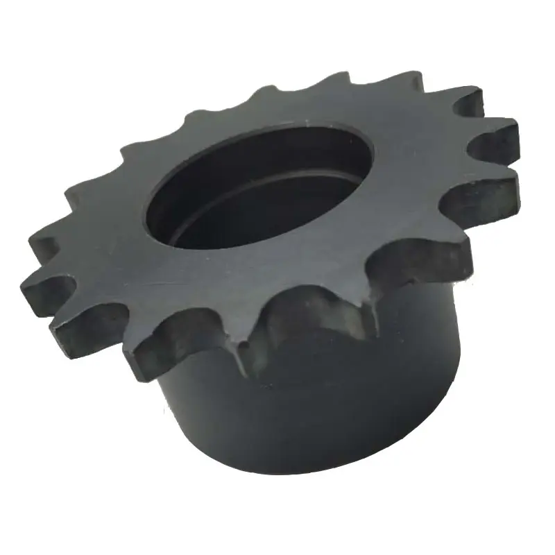
SPROCKET 1” X 17.02mm 16B SERIES SPROCKETS
| For Chain Acc.to DIN8187 ISO/R 606 | |||||
| Tooth Radius r3 | 26.0mm | ||||
| Radius Width C | 2.5mm | ||||
| Tooth Width b1 | 15.8mm | ||||
| Tooth Width B1 | 16.2mm | ||||
| Tooth Width B2 | 47.7mm | ||||
| Tooth Width B3 | 79.6mm | ||||
| 16B SERIES ROLLER CHAINS | |||||
| Pitch | 25.4 mm | ||||
| Internal Width | 17.02 mm | ||||
| Roller Diameter | 15.88mm | ||||
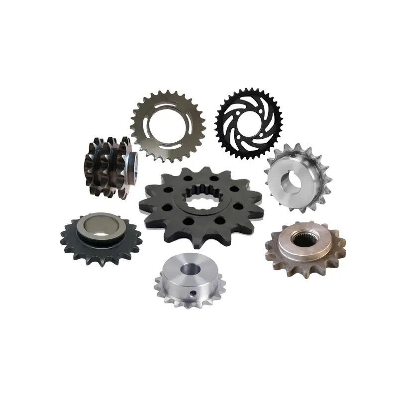
Products Show
| Z | de | dp | SIMPLEX | DUPLEX | TRIPLEX | ||||||
| dm | D1 | A | dm | D2 | A | dm | D2 | A | |||
| 8 | 77.0 | 66.37 | 42 | 16 | 35 | 42 | 16 | 65 | 42 | 20 | 95 |
| 9 | 85.0 | 74.27 | 50 | 16 | 35 | 50 | 16 | 65 | 50 | 20 | 95 |
| 10 | 93.0 | 82.19 | 55 | 16 | 35 | 56 | 16 | 65 | 56 | 20 | 95 |
| 11 | 105.1 | 90.14 | 61 | 16 | 40 | 64 | 20 | 70 | 64 | 25 | 100 |
| 12 | 109.0 | 98.14 | 69 | 16 | 40 | 72 | 20 | 70 | 72 | 25 | 100 |
| 13 | 117.0 | 106.12 | 78 | 16 | 40 | 80 | 20 | 70 | 80 | 25 | 100 |
| 14 | 125.0 | 114.15 | 84 | 16 | 40 | 88 | 20 | 70 | 88 | 25 | 100 |
| 15 | 133.0 | 122.17 | 92 | 16 | 40 | 96 | 20 | 70 | 96 | 25 | 100 |
| 16 | 141.0 | 130.20 | 100 | 20 | 45 | 104 | 20 | 70 | 104 | 25 | 100 |
| 17 | 149.0 | 138.22 | 100 | 20 | 45 | 112 | 20 | 70 | 112 | 25 | 100 |
| 18 | 157.0 | 146.28 | 100 | 20 | 45 | 120 | 20 | 70 | 120 | 25 | 100 |
| 19 | 165.2 | 154.33 | 100 | 20 | 45 | 128 | 20 | 70 | 128 | 25 | 100 |
| 20 | 173.2 | 162.38 | 100 | 20 | 45 | 130 | 20 | 70 | 130 | 25 | 100 |
| 21 | 181.2 | 170.43 | 110 | 20 | 50 | 130 | 25 | 70 | *130 | 25 | 100 |
| 22 | 189.3 | 178.48 | 110 | 20 | 50 | *130 | 25 | 70 | *130 | 25 | 100 |
| 23 | 197.5 | 186.53 | 110 | 20 | 50 | *130 | 25 | 70 | *130 | 25 | 100 |
| 24 | 205.5 | 194.59 | 110 | 20 | 50 | *130 | 25 | 70 | *130 | 25 | 100 |
| 25 | 213.5 | 202.66 | 110 | 20 | 50 | *130 | 25 | 70 | *130 | 25 | 100 |
| 26 | 221.6 | 210.72 | 120 | 20 | 50 | *130 | 25 | 70 | *130 | 30 | 100 |
| 27 | 229.6 | 218.79 | 120 | 20 | 50 | *130 | 25 | 70 | *130 | 30 | 100 |
| 28 | 237.7 | 226.85 | 120 | 20 | 50 | *130 | 25 | 70 | *130 | 30 | 100 |
| 29 | 245.8 | 234.92 | 120 | 20 | 50 | *130 | 25 | 70 | *130 | 30 | 100 |
| 30 | 254.0 | 243.00 | 120 | 20 | 50 | *130 | 25 | 70 | *130 | 30 | 100 |
| 31 | 262.0 | 251.08 | *120 | 25 | 50 | *140 | 25 | 70 | *140 | 30 | 100 |
| 32 | 270.0 | 259.13 | *120 | 25 | 50 | *140 | 25 | 70 | *140 | 30 | 100 |
| 33 | 278.5 | 267.21 | *120 | 25 | 50 | *140 | 25 | 70 | *140 | 30 | 100 |
| 34 | 287.0 | 275.28 | *120 | 25 | 50 | *140 | 25 | 70 | *140 | 30 | 100 |
| 35 | 296.2 | 283.36 | *120 | 25 | 50 | *140 | 25 | 70 | *140 | 30 | 100 |
| 36 | 304.6 | 291.44 | *120 | 25 | 50 | *140 | 25 | 70 | *140 | 30 | 100 |
| 37 | 312.6 | 299.51 | *120 | 25 | 50 | *140 | 25 | 70 | *140 | 30 | 100 |
| 38 | 320.7 | 307.59 | *120 | 25 | 50 | *140 | 25 | 70 | *140 | 30 | 100 |
| 39 | 328.8 | 315.67 | *120 | 25 | 50 | *140 | 25 | 70 | *140 | 30 | 100 |
| 40 | 336.9 | 323.75 | *120 | 25 | 50 | *140 | 25 | 70 | *140 | 30 | 100 |
| 41 | 345.0 | 331.81 | *125 | 25 | 68 | *140 | 25 | 70 | *160 | 30 | 100 |
| 42 | 353.0 | 339.89 | *125 | 25 | 68 | *140 | 25 | 70 | *160 | 30 | 100 |
| 43 | 361.1 | 347.97 | *125 | 25 | 68 | *140 | 25 | 70 | *160 | 30 | 100 |
| 44 | 369.1 | 356.05 | *125 | 25 | 68 | *140 | 25 | 70 | *160 | 30 | 100 |
| 45 | 377.1 | 364.12 | *125 | 25 | 68 | *140 | 25 | 70 | *160 | 30 | 100 |
| 46 | 385.2 | 372.20 | *125 | 25 | 68 | *140 | 25 | 70 | *160 | 30 | 100 |
| 47 | 393.2 | 380.28 | *125 | 25 | 68 | *140 | 25 | 70 | *160 | 30 | 100 |
| 48 | 401.3 | 388.36 | *125 | 25 | 68 | *140 | 25 | 70 | *160 | 30 | 100 |
| 49 | 409.3 | 396.44 | *125 | 25 | 68 | *140 | 25 | 70 | *160 | 30 | 100 |
| 50 | 417.4 | 404.52 | *125 | 25 | 68 | *140 | 25 | 70 | *160 | 30 | 100 |
| 51 | 425.5 | 412.60 | *125 | 25 | 68 | *150 | 25 | 85 | *180 | 30 | 110 |
| 52 | 433.6 | 420.68 | *125 | 25 | 68 | *150 | 25 | 85 | *180 | 30 | 110 |
| 53 | 441.7 | 428.76 | *125 | 25 | 68 | *150 | 25 | 85 | *180 | 30 | 110 |
| 54 | 448.3 | 436.84 | *125 | 25 | 68 | *150 | 25 | 85 | *180 | 30 | 110 |
| 55 | 457.9 | 444.92 | *125 | 25 | 68 | *150 | 25 | 85 | *180 | 30 | 110 |
| 56 | 466.0 | 453.01 | *125 | 25 | 68 | *150 | 25 | 85 | *180 | 30 | 110 |
| 57 | 474.0 | 461.08 | *125 | 25 | 68 | *150 | 25 | 85 | *180 | 30 | 110 |
| 58 | 482.1 | 469.16 | *133 | 25 | 68 | *150 | 25 | 85 | *180 | 30 | 110 |
| 59 | 490.2 | 477.24 | *133 | 25 | 68 | *150 | 25 | 85 | *180 | 30 | 110 |
| 60 | 498.3 | 485.23 | *133 | 25 | 68 | *150 | 25 | 85 | *180 | 30 | 110 |
| 62 | 514.5 | 501.49 | *133 | 25 | 68 | *150 | 25 | 85 | *180 | 30 | 110 |
| 64 | 530.7 | 517.65 | *140 | 25 | 68 | *160 | 25 | 90 | *180 | 30 | 110 |
| 65 | 538.8 | 525.73 | *140 | 25 | 68 | *160 | 25 | 90 | *180 | 30 | 110 |
| 66 | 546.8 | 533.80 | *140 | 25 | 68 | *160 | 25 | 90 | *180 | 30 | 110 |
| 68 | 562.9 | 549.98 | *140 | 25 | 68 | *160 | 25 | 90 | *180 | 30 | 110 |
| 70 | 579.2 | 566.15 | *140 | 25 | 68 | *160 | 25 | 90 | *180 | 30 | 110 |
| 72 | 595.4 | 582.31 | *140 | 25 | 68 | *160 | 25 | 90 | *180 | 30 | 110 |
| 75 | 619.7 | 606.56 | *140 | 25 | 68 | *160 | 25 | 90 | *180 | 30 | 110 |
| 76 | 627.0 | 614.64 | *140 | 25 | 68 | *160 | 25 | 90 | *180 | 30 | 110 |
| 78 | 643.3 | 630.81 | *140 | 25 | 68 | *160 | 25 | 90 | *180 | 30 | 110 |
| 80 | 660.0 | 646.97 | *140 | 25 | 68 | *160 | 25 | 90 | *180 | 30 | 110 |
| 85 | 699.9 | 687.39 | *140 | 25 | 78 | *160 | 25 | 90 | *180 | 30 | 110 |
| 90 | 740.3 | 727.80 | *140 | 25 | 78 | *160 | 25 | 90 | *180 | 30 | 110 |
| 95 | 781.1 | 768.22 | *140 | 25 | 78 | *160 | 25 | 90 | *180 | 30 | 110 |
| 100 | 821.1 | 808.64 | *140 | 25 | 78 | *160 | 25 | 90 | *180 | 30 | 110 |
| 110 | 902.0 | 889.48 | *140 | 25 | 78 | *160 | 25 | 90 | *180 | 30 | 110 |
| 114 | 934.3 | 921.81 | *140 | 25 | 78 | *160 | 25 | 90 | *180 | 30 | 110 |
| 120 | 982.8 | 970.32 | *140 | 25 | 78 | *160 | 25 | 90 | *180 | 30 | 110 |
| 125 | 1571.3 | 1571.73 | *140 | 25 | 78 | *160 | 25 | 90 | *180 | 30 | 110 |
Notice: *welding hub
BASIC INFO.
| Product name | DIN ISO Standard Sprocket for Roller Chain |
| Materials Available | 1. Stainless Steel: SS304, SS316, etc |
| 2. Alloy Steel: C45, 45Mn, 42CrMo, 20CrMo, etc | |
| 3. OEM according to your request | |
| Surface Treatment | Heat treatment, Quenching treatment, High frequency normalizing treatment, Polishing, Electrophoresis paint processing, Anodic oxidation treatment, etc |
| Characteristic | Fire Resistant, Oil Resistant, Heat Resistant, CZPT resistance, Oxidative resistance, Corrosion resistance, etc |
| Design criterion | ISO DIN ANSI & Customer Drawings |
| Size | Customer Drawings & ISO standard |
| Application | Industrial transmission equipment |
| Package | Wooden Case / Container and pallet, or made-to-order |
| Certificate | ISO9001: 2008 |
| Advantage | Quality first, Service first, Competitive price, Fast delivery |
| Delivery Time | 20 days for samples. 45 days for official order. |
INSTALLATION AND USING
The chain wheel, as a drive or deflection for chains, has pockets to hold the chain links with a D-profile cross section with flat side surfaces parallel to the centre plane of the chain links, and outer surfaces at right angles to the chain link centre plane. The chain links are pressed firmly against the outer surfaces and each of the side surfaces by the angled laying surfaces at the base of the pockets, and also the support surfaces of the wheel body together with the end sides of the webs formed by the leading and trailing walls of the pocket.
NOTICE
When fitting new chain spoket it is very important that a new chain is fitted at the same time, and vice versa. Using an old chain with new sprockets, or a new chain with old sprockets will cause rapid wear.
It is important if you are installing the chainwheels yourself to have the factory service manual specific to your model. Our chainwheels are made to be a direct replacement for your OEM chainwheels and as such, the installation should be performed according to your models service manual.
During use a chain will stretch (i.e. the pins will wear causing extension of the chain). Using a chain which has been stretched more than the above maximum allowance causes the chain to ride up the teeth of the sprocket. This causes damage to the tips of the chainwheels teeth, as the force transmitted by the chain is transmitted entirely through the top of the tooth, rather than the whole tooth. This results in severe wearing of the chainwheel.
FOR CHAIN STHangZhouRDS
Standards organizations (such as ANSI and ISO) maintain standards for design, dimensions, and interchangeability of transmission chains. For example, the following Table shows data from ANSI standard B29.1-2011 (Precision Power Transmission Roller Chains, Attachments, and Sprockets) developed by the American Society of Mechanical Engineers (ASME). See the references[8][9][10] for additional information.
ASME/ANSI B29.1-2011 Roller Chain Standard SizesSizePitchMaximum Roller DiameterMinimum Ultimate Tensile StrengthMeasuring Load25
| ASME/ANSI B29.1-2011 Roller Chain Standard Sizes | ||||
| Size | Pitch | Maximum Roller Diameter | Minimum Ultimate Tensile Strength | Measuring Load |
|---|---|---|---|---|
| 25 | 0.250 in (6.35 mm) | 0.130 in (3.30 mm) | 780 lb (350 kg) | 18 lb (8.2 kg) |
| 35 | 0.375 in (9.53 mm) | 0.200 in (5.08 mm) | 1,760 lb (800 kg) | 18 lb (8.2 kg) |
| 41 | 0.500 in (12.70 mm) | 0.306 in (7.77 mm) | 1,500 lb (680 kg) | 18 lb (8.2 kg) |
| 40 | 0.500 in (12.70 mm) | 0.312 in (7.92 mm) | 3,125 lb (1,417 kg) | 31 lb (14 kg) |
| 50 | 0.625 in (15.88 mm) | 0.400 in (10.16 mm) | 4,880 lb (2,210 kg) | 49 lb (22 kg) |
| 60 | 0.750 in (19.05 mm) | 0.469 in (11.91 mm) | 7,030 lb (3,190 kg) | 70 lb (32 kg) |
| 80 | 1.000 in (25.40 mm) | 0.625 in (15.88 mm) | 12,500 lb (5,700 kg) | 125 lb (57 kg) |
| 100 | 1.250 in (31.75 mm) | 0.750 in (19.05 mm) | 19,531 lb (8,859 kg) | 195 lb (88 kg) |
| 120 | 1.500 in (38.10 mm) | 0.875 in (22.23 mm) | 28,125 lb (12,757 kg) | 281 lb (127 kg) |
| 140 | 1.750 in (44.45 mm) | 1.000 in (25.40 mm) | 38,280 lb (17,360 kg) | 383 lb (174 kg) |
| 160 | 2.000 in (50.80 mm) | 1.125 in (28.58 mm) | 50,000 lb (23,000 kg) | 500 lb (230 kg) |
| 180 | 2.250 in (57.15 mm) | 1.460 in (37.08 mm) | 63,280 lb (28,700 kg) | 633 lb (287 kg) |
| 200 | 2.500 in (63.50 mm) | 1.562 in (39.67 mm) | 78,175 lb (35,460 kg) | 781 lb (354 kg) |
| 240 | 3.000 in (76.20 mm) | 1.875 in (47.63 mm) | 112,500 lb (51,000 kg) | 1,000 lb (450 kg |
For mnemonic purposes, below is another presentation of key dimensions from the same standard, expressed in fractions of an inch (which was part of the thinking behind the choice of preferred numbers in the ANSI standard):
| Pitch (inches) | Pitch expressed in eighths |
ANSI standard chain number |
Width (inches) |
|---|---|---|---|
| 1⁄4 | 2⁄8 | 25 | 1⁄8 |
| 3⁄8 | 3⁄8 | 35 | 3⁄16 |
| 1⁄2 | 4⁄8 | 41 | 1⁄4 |
| 1⁄2 | 4⁄8 | 40 | 5⁄16 |
| 5⁄8 | 5⁄8 | 50 | 3⁄8 |
| 3⁄4 | 6⁄8 | 60 | 1⁄2 |
| 1 | 8⁄8 | 80 | 5⁄8 |
Notes:
1. The pitch is the distance between roller centers. The width is the distance between the link plates (i.e. slightly more than the roller width to allow for clearance).
2. The right-hand digit of the standard denotes 0 = normal chain, 1 = lightweight chain, 5 = rollerless bushing chain.
3. The left-hand digit denotes the number of eighths of an inch that make up the pitch.
4. An “H” following the standard number denotes heavyweight chain. A hyphenated number following the standard number denotes double-strand (2), triple-strand (3), and so on. Thus 60H-3 denotes number 60 heavyweight triple-strand chain.
A typical bicycle chain (for derailleur gears) uses narrow 1⁄2-inch-pitch chain. The width of the chain is variable, and does not affect the load capacity. The more sprockets at the rear wheel (historically 3-6, nowadays 7-12 sprockets), the narrower the chain. Chains are sold according to the number of speeds they are designed to work with, for example, “10 speed chain”. Hub gear or single speed bicycles use 1/2″ x 1/8″ chains, where 1/8″ refers to the maximum thickness of a sprocket that can be used with the chain.
Typically chains with parallel shaped links have an even number of links, with each narrow link followed by a broad one. Chains built up with a uniform type of link, narrow at 1 and broad at the other end, can be made with an odd number of links, which can be an advantage to adapt to a special chainwheel-distance; on the other side such a chain tends to be not so strong.
Roller chains made using ISO standard are sometimes called as isochains.
WHY CHOOSE US
1. Reliable Quality Assurance System
2. Cutting-Edge Computer-Controlled CNC Machines
3. Bespoke Solutions from Highly Experienced Specialists
4. Customization and OEM Available for Specific Application
5. Extensive Inventory of Spare Parts and Accessories
6. Well-Developed CZPT Marketing Network
7. Efficient After-Sale Service System
The 219 sets of advanced automatic production equipment provide guarantees for high product quality. The 167 engineers and technicians with senior professional titles can design and develop products to meet the exact demands of customers, and OEM customizations are also available with us. Our sound global service network can provide customers with timely after-sales technical services.
We are not just a manufacturer and supplier, but also an industry consultant. We work pro-actively with you to offer expert advice and product recommendations in order to end up with a most cost effective product available for your specific application. The clients we serve CZPT range from end users to distributors and OEMs. Our OEM replacements can be substituted wherever necessary and suitable for both repair and new assemblies.
Q:Why choose us ?
A. we are a manufacturer, we have manufactured Chain and Sprocket for over 20 years .
B. Reliable Quality Assurance System;
C. Cutting-Edge Computer-Controlled CNC Machines;
D. Bespoke Solutions from Highly Experienced Specialists;
E. Customization and OEM Available for Specific Application;
F. Extensive Inventory of Spare Parts and Accessories;
G. Well-Developed CZPT Marketing Network;
H. Efficient After-Sale Service System
Q. what is your payment term?
A: 30% TT deposit, 70% balance T/T before shipping.
Q:Can we print our logo on your products?
A: yes, we offer OEM/ODM service, we support the customized logo, size, package,etc.
Q: Can you make chains according to my CAD drawings?
A: Yes. Besides the regular standard chains, we produce non-standard and custom-design products to meet the specific technical requirements. In reality, a sizable portion of our production capacity is assigned to make non-standard products.
Q: what is your main market?
A: North America, South America, Eastern Europe, Western Europe, Southeast Asia, Africa, Oceania, Mid East, Eastern Asia,
Q: Can I get samples from your factory?
A: Yes, Samples can be provided.
Q: If products have some quality problem, how would you deal with?
A: We will responsible for all the quality problems.
| Standard Or Nonstandard: | Nonstandard |
|---|---|
| Application: | Motor, Electric Cars, Motorcycle, Machinery, Marine, Toy, Agricultural Machinery, Car, Motor, Electric Cars, Motorcycle, Machinery |
| Hardness: | Hardened Tooth Surface |
| Samples: |
US$ 0/Piece
1 Piece(Min.Order) | Order Sample |
|---|
| Customization: |
Available
| Customized Request |
|---|
.shipping-cost-tm .tm-status-off{background: none;padding:0;color: #1470cc}
|
Shipping Cost:
Estimated freight per unit. |
about shipping cost and estimated delivery time. |
|---|
| Payment Method: |
|
|---|---|
|
Initial Payment Full Payment |
| Currency: | US$ |
|---|
| Return&refunds: | You can apply for a refund up to 30 days after receipt of the products. |
|---|
Compatibility of Chain Sprockets with Wheels
In general, chain sprockets are designed to work with specific types of wheels, and there are certain requirements for ensuring proper compatibility:
- Chain Size and Pitch: The chain sprocket must match the size and pitch of the chain it is intended to work with. For example, if you have a roller chain with a pitch of 0.625 inches, you need a sprocket with the same pitch to ensure a proper fit.
- Number of Teeth: The number of teeth on the sprocket should be compatible with the number of chain links. The chain should mesh smoothly with the sprocket without any binding or skipping.
- Tooth Profile: The tooth profile of the sprocket should match the shape of the chain’s rollers to ensure smooth engagement and minimize wear.
- Shaft Size: The center hole (bore) of the sprocket should match the diameter of the shaft it will be mounted on. Using the correct shaft size ensures a secure fit and prevents wobbling.
- Hub Configuration: Some sprockets have hubs, which are extensions on either side of the sprocket. The hub’s length and configuration should match the requirements of the specific application.
- Material and Strength: Consider the material and strength of the sprocket based on the application’s load and environmental conditions. Heavy-duty applications may require sprockets made of robust materials to withstand the forces and stresses.
It’s crucial to follow the manufacturer’s specifications and guidelines when selecting a chain sprocket for a particular wheel. Mixing incompatible sprockets and wheels can result in premature wear, inefficiencies, and potential safety hazards. If you are unsure about the compatibility, consult with the manufacturer or a knowledgeable expert to ensure you choose the right sprocket for your specific application.
Extending the Lifespan of a wheel sprocket Assembly
To ensure a long lifespan for your wheel sprocket assembly, consider the following maintenance and operational practices:
- Regular Lubrication: Apply the appropriate lubricant to the sprocket teeth and chain or belt regularly. Lubrication reduces friction, wear, and the likelihood of premature failure.
- Proper Tension: Maintain the correct tension in the chain or belt to prevent excessive stress and wear. Follow the manufacturer’s guidelines for tensioning.
- Alignment: Ensure precise alignment between the wheel sprocket. Misalignment can cause accelerated wear and increase the risk of failure.
- Inspections: Regularly inspect the wheel, sprocket, chain, or belt for signs of wear, damage, or fatigue. Replace any worn-out or damaged components promptly.
- Cleanliness: Keep the wheel sprocket assembly clean from dirt, debris, and contaminants that can contribute to wear and corrosion.
- Correct Usage: Operate the machinery within the recommended speed, load, and temperature limits specified by the manufacturer.
- Training and Operator Awareness: Ensure that equipment operators are properly trained to use the machinery correctly and are aware of maintenance procedures.
- Use Quality Components: Invest in high-quality wheels, sprockets, chains, or belts from reputable suppliers to improve durability and reliability.
- Replace Components in Sets: When replacing parts, consider replacing the entire set (e.g., chain and sprockets) to maintain uniform wear and performance.
- Address Vibration Issues: Excessive vibration can accelerate wear. Investigate and address any vibration problems promptly.
By following these practices, you can significantly extend the lifespan of your wheel sprocket assembly, reduce downtime, and enhance the overall efficiency and safety of your machinery.
Can a wheel sprocket System be Used in Bicycles and Other Vehicles?
Yes, a wheel sprocket system is commonly used in bicycles and various other vehicles. In bicycles, the wheel sprocket system is a fundamental part of the drivetrain, which transfers power from the rider’s legs to the wheels, propelling the bicycle forward.
The typical bicycle drivetrain consists of a chain, front sprockets (chainrings), rear sprockets (cassette), and the bicycle’s wheels. When the rider pedals the bicycle, the chain engages with the sprockets, and as a result, the rotational motion from the pedaling is transferred to the rear wheel.
The selection of sprocket sizes (number of teeth on chainrings and cassette) can affect the gear ratio, allowing cyclists to adjust their pedaling effort and speed to suit different terrains and riding conditions. Smaller sprockets provide easier pedaling for climbing steep hills, while larger sprockets offer higher speeds on flat or downhill sections.
Beyond bicycles, the wheel sprocket system is widely used in various other vehicles and machinery to transmit power and control speed. It can be found in motorcycles, mopeds, electric scooters, and even some small electric vehicles. Additionally, the wheel sprocket system is prevalent in industrial machinery, where precise speed control and torque transmission are essential.
The efficiency and reliability of the wheel sprocket system make it a versatile and practical choice for many vehicles and mechanical applications.


editor by CX 2023-10-27
China Custom Gearbox Transmission Belt Parts Attachment Products 15 a Series Short Pitch Precision Simplex Roller Chains and Bush Chains for Agriculture
Product Description
A Series Short pitch Precision Simplex Roller Chains & Bush Chains
| ISO/ANSI/ DIN Chain No. |
China Chain No. |
Pitch P mm |
Roller diameter
d1max |
Width between inner plates b1min mm |
Pin diameter
d2max |
Pin length | Inner plate depth h2max mm |
Plate thickness
Tmax |
Tensile strength
Qmin |
Average tensile strength Q0 kN |
Weight per meter q kg/m |
|
| Lmax mm |
Lcmax mm |
|||||||||||
| 15 | *03C | 4.7625 | 2.48 | 2.38 | 1.62 | 6.10 | 6.90 | 4.30 | 0.60 | 1.80/409 | 2.0 | 0.08 |
*Bush chain:d1 in the table indicates the external diameter of the bush
ROLLER CHAIN
Roller chain or bush roller chain is the type of chain drive most commonly used for transmission of mechanical power on many kinds of domestic, industrial and agricultural machinery, including conveyors, wire- and tube-drawing machines, printing presses, cars, motorcycles, and bicycles. It consists of a series of short cylindrical rollers held together by side links. It is driven by a toothed wheel called a sprocket. It is a simple, reliable, and efficient means of power transmission.
CONSTRUCTION OF THE CHAIN
Two different sizes of roller chain, showing construction.
There are 2 types of links alternating in the bush roller chain. The first type is inner links, having 2 inner plates held together by 2 sleeves or bushings CHINAMFG which rotate 2 rollers. Inner links alternate with the second type, the outer links, consisting of 2 outer plates held together by pins passing through the bushings of the inner links. The “bushingless” roller chain is similar in operation though not in construction; instead of separate bushings or sleeves holding the inner plates together, the plate has a tube stamped into it protruding from the hole which serves the same purpose. This has the advantage of removing 1 step in assembly of the chain.
The roller chain design reduces friction compared to simpler designs, resulting in higher efficiency and less wear. The original power transmission chain varieties lacked rollers and bushings, with both the inner and outer plates held by pins which directly contacted the sprocket teeth; however this configuration exhibited extremely rapid wear of both the sprocket teeth, and the plates where they pivoted on the pins. This problem was partially solved by the development of bushed chains, with the pins holding the outer plates passing through bushings or sleeves connecting the inner plates. This distributed the wear over a greater area; however the teeth of the sprockets still wore more rapidly than is desirable, from the sliding friction against the bushings. The addition of rollers surrounding the bushing sleeves of the chain and provided rolling contact with the teeth of the sprockets resulting in excellent resistance to wear of both sprockets and chain as well. There is even very low friction, as long as the chain is sufficiently lubricated. Continuous, clean, lubrication of roller chains is of primary importance for efficient operation as well as correct tensioning.
LUBRICATION
Many driving chains (for example, in factory equipment, or driving a camshaft inside an internal combustion engine) operate in clean environments, and thus the wearing surfaces (that is, the pins and bushings) are safe from precipitation and airborne grit, many even in a sealed environment such as an oil bath. Some roller chains are designed to have o-rings built into the space between the outside link plate and the inside roller link plates. Chain manufacturers began to include this feature in 1971 after the application was invented by Joseph Montano while working for Whitney Chain of Hartford, Connecticut. O-rings were included as a way to improve lubrication to the links of power transmission chains, a service that is vitally important to extending their working life. These rubber fixtures form a barrier that holds factory applied lubricating grease inside the pin and bushing wear areas. Further, the rubber o-rings prevent dirt and other contaminants from entering inside the chain linkages, where such particles would otherwise cause significant wear.[citation needed]
There are also many chains that have to operate in dirty conditions, and for size or operational reasons cannot be sealed. Examples include chains on farm equipment, bicycles, and chain saws. These chains will necessarily have relatively high rates of wear, particularly when the operators are prepared to accept more friction, less efficiency, more noise and more frequent replacement as they neglect lubrication and adjustment.
Many oil-based lubricants attract dirt and other particles, eventually forming an CHINAMFG paste that will compound wear on chains. This problem can be circumvented by use of a “dry” PTFE spray, which forms a solid film after application and repels both particles and moisture.
VARIANTS DESIGN
Layout of a roller chain: 1. Outer plate, 2. Inner plate, 3. Pin, 4. Bushing, 5. Roller
If the chain is not being used for a high wear application (for instance if it is just transmitting motion from a hand-operated lever to a control shaft on a machine, or a sliding door on an oven), then 1 of the simpler types of chain may still be used. Conversely, where extra strength but the smooth drive of a smaller pitch is required, the chain may be “siamesed”; instead of just 2 rows of plates on the outer sides of the chain, there may be 3 (“duplex”), 4 (“triplex”), or more rows of plates running parallel, with bushings and rollers between each adjacent pair, and the same number of rows of teeth running in parallel on the sprockets to match. Timing chains on automotive engines, for example, typically have multiple rows of plates called strands.
Roller chain is made in several sizes, the most common American National Standards Institute (ANSI) standards being 40, 50, 60, and 80. The first digit(s) indicate the pitch of the chain in eighths of an inch, with the last digit being 0 for standard chain, 1 for lightweight chain, and 5 for bushed chain with no rollers. Thus, a chain with half-inch pitch would be a #40 while a #160 sprocket would have teeth spaced 2 inches apart, etc. Metric pitches are expressed in sixteenths of an inch; thus a metric #8 chain (08B-1) would be equivalent to an ANSI #40. Most roller chain is made from plain carbon or alloy steel, but stainless steel is used in food processing machinery or other places where lubrication is a problem, and nylon or brass are occasionally seen for the same reason.
Roller chain is ordinarily hooked up using a master link (also known as a connecting link), which typically has 1 pin held by a horseshoe clip rather than friction fit, allowing it to be inserted or removed with simple tools. Chain with a removable link or pin is also known as cottered chain, which allows the length of the chain to be adjusted. Half links (also known as offsets) are available and are used to increase the length of the chain by a single roller. Riveted roller chain has the master link (also known as a connecting link) “riveted” or mashed on the ends. These pins are made to be durable and are not removable.
USE
An example of 2 ‘ghost’ sprockets tensioning a triplex roller chain system
Roller chains are used in low- to mid-speed drives at around 600 to 800 feet per minute; however, at higher speeds, around 2,000 to 3,000 feet per minute, V-belts are normally used due to wear and noise issues.
A bicycle chain is a form of roller chain. Bicycle chains may have a master link, or may require a chain tool for removal and installation. A similar but larger and thus stronger chain is used on most motorcycles although it is sometimes replaced by either a toothed belt or a shaft drive, which offer lower noise level and fewer maintenance requirements.
The great majority of automobile engines use roller chains to drive the camshaft(s). Very high performance engines often use gear drive, and starting in the early 1960s toothed belts were used by some manufacturers.
Chains are also used in forklifts using hydraulic rams as a pulley to raise and lower the carriage; however, these chains are not considered roller chains, but are classified as lift or leaf chains.
Chainsaw cutting chains superficially resemble roller chains but are more closely related to leaf chains. They are driven by projecting drive links which also serve to locate the chain CHINAMFG the bar.
Sea Harrier FA.2 ZA195 front (cold) vector thrust nozzle – the nozzle is rotated by a chain drive from an air motor
A perhaps unusual use of a pair of motorcycle chains is in the Harrier Jump Jet, where a chain drive from an air motor is used to rotate the movable engine nozzles, allowing them to be pointed downwards for hovering flight, or to the rear for normal CHINAMFG flight, a system known as Thrust vectoring.
WEAR
The effect of wear on a roller chain is to increase the pitch (spacing of the links), causing the chain to grow longer. Note that this is due to wear at the pivoting pins and bushes, not from actual stretching of the metal (as does happen to some flexible steel components such as the hand-brake cable of a motor vehicle).
With modern chains it is unusual for a chain (other than that of a bicycle) to wear until it breaks, since a worn chain leads to the rapid onset of wear on the teeth of the sprockets, with ultimate failure being the loss of all the teeth on the sprocket. The sprockets (in particular the smaller of the two) suffer a grinding motion that puts a characteristic hook shape into the driven face of the teeth. (This effect is made worse by a chain improperly tensioned, but is unavoidable no matter what care is taken). The worn teeth (and chain) no longer provides smooth transmission of power and this may become evident from the noise, the vibration or (in car engines using a timing chain) the variation in ignition timing seen with a timing light. Both sprockets and chain should be replaced in these cases, since a new chain on worn sprockets will not last long. However, in less severe cases it may be possible to save the larger of the 2 sprockets, since it is always the smaller 1 that suffers the most wear. Only in very light-weight applications such as a bicycle, or in extreme cases of improper tension, will the chain normally jump off the sprockets.
The lengthening due to wear of a chain is calculated by the following formula:
M = the length of a number of links measured
S = the number of links measured
P = Pitch
In industry, it is usual to monitor the movement of the chain tensioner (whether manual or automatic) or the exact length of a drive chain (one rule of thumb is to replace a roller chain which has elongated 3% on an adjustable drive or 1.5% on a fixed-center drive). A simpler method, particularly suitable for the cycle or motorcycle user, is to attempt to pull the chain away from the larger of the 2 sprockets, whilst ensuring the chain is taut. Any significant movement (e.g. making it possible to see through a gap) probably indicates a chain worn up to and beyond the limit. Sprocket damage will result if the problem is ignored. Sprocket wear cancels this effect, and may mask chain wear.
CHAIN STRENGTH
The most common measure of roller chain’s strength is tensile strength. Tensile strength represents how much load a chain can withstand under a one-time load before breaking. Just as important as tensile strength is a chain’s fatigue strength. The critical factors in a chain’s fatigue strength is the quality of steel used to manufacture the chain, the heat treatment of the chain components, the quality of the pitch hole fabrication of the linkplates, and the type of shot plus the intensity of shot peen coverage on the linkplates. Other factors can include the thickness of the linkplates and the design (contour) of the linkplates. The rule of thumb for roller chain operating on a continuous drive is for the chain load to not exceed a mere 1/6 or 1/9 of the chain’s tensile strength, depending on the type of master links used (press-fit vs. slip-fit)[citation needed]. Roller chains operating on a continuous drive beyond these thresholds can and typically do fail prematurely via linkplate fatigue failure.
The standard minimum ultimate strength of the ANSI 29.1 steel chain is 12,500 x (pitch, in inches)2. X-ring and O-Ring chains greatly decrease wear by means of internal lubricants, increasing chain life. The internal lubrication is inserted by means of a vacuum when riveting the chain together.
CHAIN STHangZhouRDS
Standards organizations (such as ANSI and ISO) maintain standards for design, dimensions, and interchangeability of transmission chains. For example, the following Table shows data from ANSI standard B29.1-2011 (Precision Power Transmission Roller Chains, Attachments, and Sprockets) developed by the American Society of Mechanical Engineers (ASME). See the references[8][9][10] for additional information.
ASME/ANSI B29.1-2011 Roller Chain Standard SizesSizePitchMaximum Roller DiameterMinimum Ultimate Tensile StrengthMeasuring Load25
| ASME/ANSI B29.1-2011 Roller Chain Standard Sizes | ||||
| Size | Pitch | Maximum Roller Diameter | Minimum Ultimate Tensile Strength | Measuring Load |
|---|---|---|---|---|
| 25 | 0.250 in (6.35 mm) | 0.130 in (3.30 mm) | 780 lb (350 kg) | 18 lb (8.2 kg) |
| 35 | 0.375 in (9.53 mm) | 0.200 in (5.08 mm) | 1,760 lb (800 kg) | 18 lb (8.2 kg) |
| 41 | 0.500 in (12.70 mm) | 0.306 in (7.77 mm) | 1,500 lb (680 kg) | 18 lb (8.2 kg) |
| 40 | 0.500 in (12.70 mm) | 0.312 in (7.92 mm) | 3,125 lb (1,417 kg) | 31 lb (14 kg) |
| 50 | 0.625 in (15.88 mm) | 0.400 in (10.16 mm) | 4,880 lb (2,210 kg) | 49 lb (22 kg) |
| 60 | 0.750 in (19.05 mm) | 0.469 in (11.91 mm) | 7,030 lb (3,190 kg) | 70 lb (32 kg) |
| 80 | 1.000 in (25.40 mm) | 0.625 in (15.88 mm) | 12,500 lb (5,700 kg) | 125 lb (57 kg) |
| 100 | 1.250 in (31.75 mm) | 0.750 in (19.05 mm) | 19,531 lb (8,859 kg) | 195 lb (88 kg) |
| 120 | 1.500 in (38.10 mm) | 0.875 in (22.23 mm) | 28,125 lb (12,757 kg) | 281 lb (127 kg) |
| 140 | 1.750 in (44.45 mm) | 1.000 in (25.40 mm) | 38,280 lb (17,360 kg) | 383 lb (174 kg) |
| 160 | 2.000 in (50.80 mm) | 1.125 in (28.58 mm) | 50,000 lb (23,000 kg) | 500 lb (230 kg) |
| 180 | 2.250 in (57.15 mm) | 1.460 in (37.08 mm) | 63,280 lb (28,700 kg) | 633 lb (287 kg) |
| 200 | 2.500 in (63.50 mm) | 1.562 in (39.67 mm) | 78,175 lb (35,460 kg) | 781 lb (354 kg) |
| 240 | 3.000 in (76.20 mm) | 1.875 in (47.63 mm) | 112,500 lb (51,000 kg) | 1,000 lb (450 kg |
For mnemonic purposes, below is another presentation of key dimensions from the same standard, expressed in fractions of an inch (which was part of the thinking behind the choice of preferred numbers in the ANSI standard):
| Pitch (inches) | Pitch expressed in eighths |
ANSI standard chain number |
Width (inches) |
|---|---|---|---|
| 1⁄4 | 2⁄8 | 25 | 1⁄8 |
| 3⁄8 | 3⁄8 | 35 | 3⁄16 |
| 1⁄2 | 4⁄8 | 41 | 1⁄4 |
| 1⁄2 | 4⁄8 | 40 | 5⁄16 |
| 5⁄8 | 5⁄8 | 50 | 3⁄8 |
| 3⁄4 | 6⁄8 | 60 | 1⁄2 |
| 1 | 8⁄8 | 80 | 5⁄8 |
Notes:
1. The pitch is the distance between roller centers. The width is the distance between the link plates (i.e. slightly more than the roller width to allow for clearance).
2. The right-hand digit of the standard denotes 0 = normal chain, 1 = lightweight chain, 5 = rollerless bushing chain.
3. The left-hand digit denotes the number of eighths of an inch that make up the pitch.
4. An “H” following the standard number denotes heavyweight chain. A hyphenated number following the standard number denotes double-strand (2), triple-strand (3), and so on. Thus 60H-3 denotes number 60 heavyweight triple-strand chain.
A typical bicycle chain (for derailleur gears) uses narrow 1⁄2-inch-pitch chain. The width of the chain is variable, and does not affect the load capacity. The more sprockets at the rear wheel (historically 3-6, nowadays 7-12 sprockets), the narrower the chain. Chains are sold according to the number of speeds they are designed to work with, for example, “10 speed chain”. Hub gear or single speed bicycles use 1/2″ x 1/8″ chains, where 1/8″ refers to the maximum thickness of a sprocket that can be used with the chain.
Typically chains with parallel shaped links have an even number of links, with each narrow link followed by a broad one. Chains built up with a uniform type of link, narrow at 1 and broad at the other end, can be made with an odd number of links, which can be an advantage to adapt to a special chainwheel-distance; on the other side such a chain tends to be not so strong.
Roller chains made using ISO standard are sometimes called as isochains.
WHY CHOOSE US
1. Reliable Quality Assurance System
2. Cutting-Edge Computer-Controlled CNC Machines
3. Bespoke Solutions from Highly Experienced Specialists
4. Customization and OEM Available for Specific Application
5. Extensive Inventory of Spare Parts and Accessories
6. Well-Developed CHINAMFG Marketing Network
7. Efficient After-Sale Service System
The 219 sets of advanced automatic production equipment provide guarantees for high product quality. The 167 engineers and technicians with senior professional titles can design and develop products to meet the exact demands of customers, and OEM customizations are also available with us. Our sound global service network can provide customers with timely after-sales technical services.
We are not just a manufacturer and supplier, but also an industry consultant. We work pro-actively with you to offer expert advice and product recommendations in order to end up with a most cost effective product available for your specific application. The clients we serve CHINAMFG range from end users to distributors and OEMs. Our OEM replacements can be substituted wherever necessary and suitable for both repair and new assemblies.
| Standard or Nonstandard: | Standard |
|---|---|
| Application: | Textile Machinery, Garment Machinery, Conveyer Equipment, Packaging Machinery, Electric Cars, Motorcycle, Food Machinery, Marine, Mining Equipment, Agricultural Machinery, Car |
| Surface Treatment: | Polishing |
| Samples: |
US$ 3/Meter
1 Meter(Min.Order) | Order Sample |
|---|
| Customization: |
Available
| Customized Request |
|---|
.shipping-cost-tm .tm-status-off{background: none;padding:0;color: #1470cc}
|
Shipping Cost:
Estimated freight per unit. |
about shipping cost and estimated delivery time. |
|---|
| Payment Method: |
|
|---|---|
|
Initial Payment Full Payment |
| Currency: | US$ |
|---|
| Return&refunds: | You can apply for a refund up to 30 days after receipt of the products. |
|---|
Can transmission chains be used in marine or offshore applications?
Yes, transmission chains can be used in marine or offshore applications. Here’s a detailed answer to the question:
1. Corrosion Resistance: Transmission chains used in marine or offshore applications are typically made from materials that offer high corrosion resistance, such as stainless steel or specially coated chains. These chains are designed to withstand the corrosive effects of s altwater, moisture, and other harsh environmental conditions.
2. Sealing and Protection: In marine or offshore environments, transmission chains are often equipped with additional sealing and protection measures. This can include seals, covers, or special coatings that provide an extra layer of defense against water, debris, and contaminants.
3. High Load Capacity: Marine and offshore applications often involve heavy-duty operations, such as lifting or pulling heavy loads. Transmission chains used in these applications are designed to handle high loads and provide reliable power transmission.
4. Resistance to Harsh Conditions: Marine and offshore environments can be challenging, with factors like high humidity, extreme temperatures, and exposure to s altwater and abrasive substances. Transmission chains for these applications are engineered to withstand these harsh conditions and maintain their performance and durability.
5. Compliance with Industry Standards: Transmission chains used in marine or offshore applications may need to meet specific industry standards and regulations. These standards ensure that the chains are suitable for the demanding conditions and safety requirements of the marine and offshore industries.
It’s important to select transmission chains specifically designed for marine or offshore applications to ensure reliable and long-lasting performance. Consulting with experts in the field and following manufacturer guidelines for installation, maintenance, and inspection is essential to maximize the effectiveness and lifespan of the transmission chains in these environments.
What are the advantages of using a lubrication-free transmission chain?
Using a lubrication-free transmission chain offers several benefits. Here’s a detailed answer to the question:
1. Maintenance-free Operation: Lubrication-free transmission chains eliminate the need for regular lubrication and maintenance. This saves time, reduces maintenance costs, and minimizes downtime associated with lubrication tasks.
2. Clean and Environmentally Friendly: Lubrication-free chains operate without the need for external lubricants, which eliminates the risk of oil or grease contamination in the surrounding environment. This is particularly advantageous in applications where cleanliness is crucial, such as in food processing, pharmaceutical, or cleanroom environments.
3. Reduced Friction and Wear: Lubrication-free chains are designed with self-lubricating materials or coatings that offer low friction and excellent wear resistance. These chains are specifically engineered to provide long-lasting performance without the need for external lubrication. The reduced friction and wear contribute to extended chain life and improved efficiency.
4. Enhanced Reliability: Lubrication-free transmission chains provide consistent and reliable performance, as they are not dependent on external lubrication that can deteriorate or deplete over time. They are designed to withstand various operating conditions and maintain their performance even in the absence of lubrication.
5. Wide Range of Applications: Lubrication-free transmission chains are suitable for a wide range of applications across different industries. They are commonly used in industries such as food and beverage, packaging, medical equipment, textile, and electronics, where lubrication may not be feasible or desirable.
6. Improved Cleanliness and Safety: Lubrication-free chains contribute to a cleaner working environment by eliminating the risk of oil or grease leaks. This enhances workplace safety, reduces the potential for slip hazards, and ensures compliance with stringent cleanliness standards.
It’s important to note that lubrication-free chains are designed and manufactured using specialized materials and coatings to provide the necessary self-lubricating properties. It’s essential to choose the appropriate lubrication-free chain based on the specific application requirements and operating conditions.
What are the maintenance requirements for transmission chains?
Maintenance plays a crucial role in ensuring the optimal performance and longevity of transmission chains. Here’s a detailed explanation:
1. Regular Inspection: Regular visual inspections should be conducted to check for any signs of wear, damage, or misalignment. Inspect the chain for signs of elongation, corrosion, broken or damaged links, and excessive wear on the sprockets.
2. Lubrication: Proper lubrication is essential to minimize friction, reduce wear, and extend the life of the chain. Follow the manufacturer’s recommendations for the type and frequency of lubrication. Apply lubricant evenly along the entire length of the chain, ensuring that it penetrates between the components.
3. Tensioning: Maintaining the correct tension in the chain is important for smooth operation and to prevent chain slippage. Follow the manufacturer’s guidelines for the recommended tensioning method and the appropriate tension level. Check the tension regularly and adjust as necessary.
4. Cleaning: Regular cleaning helps remove dirt, debris, and contaminants that can accelerate wear and cause chain failure. Use a suitable cleaning agent or solvent to clean the chain, and ensure it is thoroughly dry before applying lubrication.
5. Alignment: Proper alignment between the chain and the sprockets is crucial for smooth operation and to prevent premature wear. Check the alignment regularly and make any necessary adjustments to ensure the chain runs straight and smoothly along the sprockets.
6. Replacement of Worn Components: Over time, transmission chains may experience wear and elongation. It is important to replace worn-out components such as links, pins, and sprockets to maintain the proper functioning of the chain.
7. Environmental Considerations: Consider the operating environment of the transmission chain and take appropriate measures to protect it from corrosive substances, extreme temperatures, or excessive humidity. Apply corrosion-resistant coatings or use stainless steel chains when necessary.
8. Record Keeping: Maintain a record of maintenance activities, including lubrication schedules, tension adjustments, inspections, and component replacements. This record will help track the maintenance history and identify any patterns or issues that may arise.
It is important to consult the manufacturer’s guidelines and recommendations for specific maintenance requirements based on the type and model of the transmission chain. Adhering to proper maintenance practices will help ensure the reliability, performance, and longevity of the transmission chain in various applications.
editor by CX 2023-10-26
China supplier Gearbox Transmission Belt Parts Attachment Products 15 a Series Short Pitch Precision Simplex Roller Chains and Bush Chains for Agriculture
Product Description
A Series Short pitch Precision Simplex Roller Chains & Bush Chains
| ISO/ANSI/ DIN Chain No. |
China Chain No. |
Pitch P mm |
Roller diameter
d1max |
Width between inner plates b1min mm |
Pin diameter
d2max |
Pin length | Inner plate depth h2max mm |
Plate thickness
Tmax |
Tensile strength
Qmin |
Average tensile strength Q0 kN |
Weight per meter q kg/m |
|
| Lmax mm |
Lcmax mm |
|||||||||||
| 15 | *03C | 4.7625 | 2.48 | 2.38 | 1.62 | 6.10 | 6.90 | 4.30 | 0.60 | 1.80/409 | 2.0 | 0.08 |
*Bush chain:d1 in the table indicates the external diameter of the bush
ROLLER CHAIN
Roller chain or bush roller chain is the type of chain drive most commonly used for transmission of mechanical power on many kinds of domestic, industrial and agricultural machinery, including conveyors, wire- and tube-drawing machines, printing presses, cars, motorcycles, and bicycles. It consists of a series of short cylindrical rollers held together by side links. It is driven by a toothed wheel called a sprocket. It is a simple, reliable, and efficient means of power transmission.
CONSTRUCTION OF THE CHAIN
Two different sizes of roller chain, showing construction.
There are 2 types of links alternating in the bush roller chain. The first type is inner links, having 2 inner plates held together by 2 sleeves or bushings CHINAMFG which rotate 2 rollers. Inner links alternate with the second type, the outer links, consisting of 2 outer plates held together by pins passing through the bushings of the inner links. The “bushingless” roller chain is similar in operation though not in construction; instead of separate bushings or sleeves holding the inner plates together, the plate has a tube stamped into it protruding from the hole which serves the same purpose. This has the advantage of removing 1 step in assembly of the chain.
The roller chain design reduces friction compared to simpler designs, resulting in higher efficiency and less wear. The original power transmission chain varieties lacked rollers and bushings, with both the inner and outer plates held by pins which directly contacted the sprocket teeth; however this configuration exhibited extremely rapid wear of both the sprocket teeth, and the plates where they pivoted on the pins. This problem was partially solved by the development of bushed chains, with the pins holding the outer plates passing through bushings or sleeves connecting the inner plates. This distributed the wear over a greater area; however the teeth of the sprockets still wore more rapidly than is desirable, from the sliding friction against the bushings. The addition of rollers surrounding the bushing sleeves of the chain and provided rolling contact with the teeth of the sprockets resulting in excellent resistance to wear of both sprockets and chain as well. There is even very low friction, as long as the chain is sufficiently lubricated. Continuous, clean, lubrication of roller chains is of primary importance for efficient operation as well as correct tensioning.
LUBRICATION
Many driving chains (for example, in factory equipment, or driving a camshaft inside an internal combustion engine) operate in clean environments, and thus the wearing surfaces (that is, the pins and bushings) are safe from precipitation and airborne grit, many even in a sealed environment such as an oil bath. Some roller chains are designed to have o-rings built into the space between the outside link plate and the inside roller link plates. Chain manufacturers began to include this feature in 1971 after the application was invented by Joseph Montano while working for Whitney Chain of Hartford, Connecticut. O-rings were included as a way to improve lubrication to the links of power transmission chains, a service that is vitally important to extending their working life. These rubber fixtures form a barrier that holds factory applied lubricating grease inside the pin and bushing wear areas. Further, the rubber o-rings prevent dirt and other contaminants from entering inside the chain linkages, where such particles would otherwise cause significant wear.[citation needed]
There are also many chains that have to operate in dirty conditions, and for size or operational reasons cannot be sealed. Examples include chains on farm equipment, bicycles, and chain saws. These chains will necessarily have relatively high rates of wear, particularly when the operators are prepared to accept more friction, less efficiency, more noise and more frequent replacement as they neglect lubrication and adjustment.
Many oil-based lubricants attract dirt and other particles, eventually forming an CHINAMFG paste that will compound wear on chains. This problem can be circumvented by use of a “dry” PTFE spray, which forms a solid film after application and repels both particles and moisture.
VARIANTS DESIGN
Layout of a roller chain: 1. Outer plate, 2. Inner plate, 3. Pin, 4. Bushing, 5. Roller
If the chain is not being used for a high wear application (for instance if it is just transmitting motion from a hand-operated lever to a control shaft on a machine, or a sliding door on an oven), then 1 of the simpler types of chain may still be used. Conversely, where extra strength but the smooth drive of a smaller pitch is required, the chain may be “siamesed”; instead of just 2 rows of plates on the outer sides of the chain, there may be 3 (“duplex”), 4 (“triplex”), or more rows of plates running parallel, with bushings and rollers between each adjacent pair, and the same number of rows of teeth running in parallel on the sprockets to match. Timing chains on automotive engines, for example, typically have multiple rows of plates called strands.
Roller chain is made in several sizes, the most common American National Standards Institute (ANSI) standards being 40, 50, 60, and 80. The first digit(s) indicate the pitch of the chain in eighths of an inch, with the last digit being 0 for standard chain, 1 for lightweight chain, and 5 for bushed chain with no rollers. Thus, a chain with half-inch pitch would be a #40 while a #160 sprocket would have teeth spaced 2 inches apart, etc. Metric pitches are expressed in sixteenths of an inch; thus a metric #8 chain (08B-1) would be equivalent to an ANSI #40. Most roller chain is made from plain carbon or alloy steel, but stainless steel is used in food processing machinery or other places where lubrication is a problem, and nylon or brass are occasionally seen for the same reason.
Roller chain is ordinarily hooked up using a master link (also known as a connecting link), which typically has 1 pin held by a horseshoe clip rather than friction fit, allowing it to be inserted or removed with simple tools. Chain with a removable link or pin is also known as cottered chain, which allows the length of the chain to be adjusted. Half links (also known as offsets) are available and are used to increase the length of the chain by a single roller. Riveted roller chain has the master link (also known as a connecting link) “riveted” or mashed on the ends. These pins are made to be durable and are not removable.
USE
An example of 2 ‘ghost’ sprockets tensioning a triplex roller chain system
Roller chains are used in low- to mid-speed drives at around 600 to 800 feet per minute; however, at higher speeds, around 2,000 to 3,000 feet per minute, V-belts are normally used due to wear and noise issues.
A bicycle chain is a form of roller chain. Bicycle chains may have a master link, or may require a chain tool for removal and installation. A similar but larger and thus stronger chain is used on most motorcycles although it is sometimes replaced by either a toothed belt or a shaft drive, which offer lower noise level and fewer maintenance requirements.
The great majority of automobile engines use roller chains to drive the camshaft(s). Very high performance engines often use gear drive, and starting in the early 1960s toothed belts were used by some manufacturers.
Chains are also used in forklifts using hydraulic rams as a pulley to raise and lower the carriage; however, these chains are not considered roller chains, but are classified as lift or leaf chains.
Chainsaw cutting chains superficially resemble roller chains but are more closely related to leaf chains. They are driven by projecting drive links which also serve to locate the chain CHINAMFG the bar.
Sea Harrier FA.2 ZA195 front (cold) vector thrust nozzle – the nozzle is rotated by a chain drive from an air motor
A perhaps unusual use of a pair of motorcycle chains is in the Harrier Jump Jet, where a chain drive from an air motor is used to rotate the movable engine nozzles, allowing them to be pointed downwards for hovering flight, or to the rear for normal CHINAMFG flight, a system known as Thrust vectoring.
WEAR
The effect of wear on a roller chain is to increase the pitch (spacing of the links), causing the chain to grow longer. Note that this is due to wear at the pivoting pins and bushes, not from actual stretching of the metal (as does happen to some flexible steel components such as the hand-brake cable of a motor vehicle).
With modern chains it is unusual for a chain (other than that of a bicycle) to wear until it breaks, since a worn chain leads to the rapid onset of wear on the teeth of the sprockets, with ultimate failure being the loss of all the teeth on the sprocket. The sprockets (in particular the smaller of the two) suffer a grinding motion that puts a characteristic hook shape into the driven face of the teeth. (This effect is made worse by a chain improperly tensioned, but is unavoidable no matter what care is taken). The worn teeth (and chain) no longer provides smooth transmission of power and this may become evident from the noise, the vibration or (in car engines using a timing chain) the variation in ignition timing seen with a timing light. Both sprockets and chain should be replaced in these cases, since a new chain on worn sprockets will not last long. However, in less severe cases it may be possible to save the larger of the 2 sprockets, since it is always the smaller 1 that suffers the most wear. Only in very light-weight applications such as a bicycle, or in extreme cases of improper tension, will the chain normally jump off the sprockets.
The lengthening due to wear of a chain is calculated by the following formula:
M = the length of a number of links measured
S = the number of links measured
P = Pitch
In industry, it is usual to monitor the movement of the chain tensioner (whether manual or automatic) or the exact length of a drive chain (one rule of thumb is to replace a roller chain which has elongated 3% on an adjustable drive or 1.5% on a fixed-center drive). A simpler method, particularly suitable for the cycle or motorcycle user, is to attempt to pull the chain away from the larger of the 2 sprockets, whilst ensuring the chain is taut. Any significant movement (e.g. making it possible to see through a gap) probably indicates a chain worn up to and beyond the limit. Sprocket damage will result if the problem is ignored. Sprocket wear cancels this effect, and may mask chain wear.
CHAIN STRENGTH
The most common measure of roller chain’s strength is tensile strength. Tensile strength represents how much load a chain can withstand under a one-time load before breaking. Just as important as tensile strength is a chain’s fatigue strength. The critical factors in a chain’s fatigue strength is the quality of steel used to manufacture the chain, the heat treatment of the chain components, the quality of the pitch hole fabrication of the linkplates, and the type of shot plus the intensity of shot peen coverage on the linkplates. Other factors can include the thickness of the linkplates and the design (contour) of the linkplates. The rule of thumb for roller chain operating on a continuous drive is for the chain load to not exceed a mere 1/6 or 1/9 of the chain’s tensile strength, depending on the type of master links used (press-fit vs. slip-fit)[citation needed]. Roller chains operating on a continuous drive beyond these thresholds can and typically do fail prematurely via linkplate fatigue failure.
The standard minimum ultimate strength of the ANSI 29.1 steel chain is 12,500 x (pitch, in inches)2. X-ring and O-Ring chains greatly decrease wear by means of internal lubricants, increasing chain life. The internal lubrication is inserted by means of a vacuum when riveting the chain together.
CHAIN STHangZhouRDS
Standards organizations (such as ANSI and ISO) maintain standards for design, dimensions, and interchangeability of transmission chains. For example, the following Table shows data from ANSI standard B29.1-2011 (Precision Power Transmission Roller Chains, Attachments, and Sprockets) developed by the American Society of Mechanical Engineers (ASME). See the references[8][9][10] for additional information.
ASME/ANSI B29.1-2011 Roller Chain Standard SizesSizePitchMaximum Roller DiameterMinimum Ultimate Tensile StrengthMeasuring Load25
| ASME/ANSI B29.1-2011 Roller Chain Standard Sizes | ||||
| Size | Pitch | Maximum Roller Diameter | Minimum Ultimate Tensile Strength | Measuring Load |
|---|---|---|---|---|
| 25 | 0.250 in (6.35 mm) | 0.130 in (3.30 mm) | 780 lb (350 kg) | 18 lb (8.2 kg) |
| 35 | 0.375 in (9.53 mm) | 0.200 in (5.08 mm) | 1,760 lb (800 kg) | 18 lb (8.2 kg) |
| 41 | 0.500 in (12.70 mm) | 0.306 in (7.77 mm) | 1,500 lb (680 kg) | 18 lb (8.2 kg) |
| 40 | 0.500 in (12.70 mm) | 0.312 in (7.92 mm) | 3,125 lb (1,417 kg) | 31 lb (14 kg) |
| 50 | 0.625 in (15.88 mm) | 0.400 in (10.16 mm) | 4,880 lb (2,210 kg) | 49 lb (22 kg) |
| 60 | 0.750 in (19.05 mm) | 0.469 in (11.91 mm) | 7,030 lb (3,190 kg) | 70 lb (32 kg) |
| 80 | 1.000 in (25.40 mm) | 0.625 in (15.88 mm) | 12,500 lb (5,700 kg) | 125 lb (57 kg) |
| 100 | 1.250 in (31.75 mm) | 0.750 in (19.05 mm) | 19,531 lb (8,859 kg) | 195 lb (88 kg) |
| 120 | 1.500 in (38.10 mm) | 0.875 in (22.23 mm) | 28,125 lb (12,757 kg) | 281 lb (127 kg) |
| 140 | 1.750 in (44.45 mm) | 1.000 in (25.40 mm) | 38,280 lb (17,360 kg) | 383 lb (174 kg) |
| 160 | 2.000 in (50.80 mm) | 1.125 in (28.58 mm) | 50,000 lb (23,000 kg) | 500 lb (230 kg) |
| 180 | 2.250 in (57.15 mm) | 1.460 in (37.08 mm) | 63,280 lb (28,700 kg) | 633 lb (287 kg) |
| 200 | 2.500 in (63.50 mm) | 1.562 in (39.67 mm) | 78,175 lb (35,460 kg) | 781 lb (354 kg) |
| 240 | 3.000 in (76.20 mm) | 1.875 in (47.63 mm) | 112,500 lb (51,000 kg) | 1,000 lb (450 kg |
For mnemonic purposes, below is another presentation of key dimensions from the same standard, expressed in fractions of an inch (which was part of the thinking behind the choice of preferred numbers in the ANSI standard):
| Pitch (inches) | Pitch expressed in eighths |
ANSI standard chain number |
Width (inches) |
|---|---|---|---|
| 1⁄4 | 2⁄8 | 25 | 1⁄8 |
| 3⁄8 | 3⁄8 | 35 | 3⁄16 |
| 1⁄2 | 4⁄8 | 41 | 1⁄4 |
| 1⁄2 | 4⁄8 | 40 | 5⁄16 |
| 5⁄8 | 5⁄8 | 50 | 3⁄8 |
| 3⁄4 | 6⁄8 | 60 | 1⁄2 |
| 1 | 8⁄8 | 80 | 5⁄8 |
Notes:
1. The pitch is the distance between roller centers. The width is the distance between the link plates (i.e. slightly more than the roller width to allow for clearance).
2. The right-hand digit of the standard denotes 0 = normal chain, 1 = lightweight chain, 5 = rollerless bushing chain.
3. The left-hand digit denotes the number of eighths of an inch that make up the pitch.
4. An “H” following the standard number denotes heavyweight chain. A hyphenated number following the standard number denotes double-strand (2), triple-strand (3), and so on. Thus 60H-3 denotes number 60 heavyweight triple-strand chain.
A typical bicycle chain (for derailleur gears) uses narrow 1⁄2-inch-pitch chain. The width of the chain is variable, and does not affect the load capacity. The more sprockets at the rear wheel (historically 3-6, nowadays 7-12 sprockets), the narrower the chain. Chains are sold according to the number of speeds they are designed to work with, for example, “10 speed chain”. Hub gear or single speed bicycles use 1/2″ x 1/8″ chains, where 1/8″ refers to the maximum thickness of a sprocket that can be used with the chain.
Typically chains with parallel shaped links have an even number of links, with each narrow link followed by a broad one. Chains built up with a uniform type of link, narrow at 1 and broad at the other end, can be made with an odd number of links, which can be an advantage to adapt to a special chainwheel-distance; on the other side such a chain tends to be not so strong.
Roller chains made using ISO standard are sometimes called as isochains.
WHY CHOOSE US
1. Reliable Quality Assurance System
2. Cutting-Edge Computer-Controlled CNC Machines
3. Bespoke Solutions from Highly Experienced Specialists
4. Customization and OEM Available for Specific Application
5. Extensive Inventory of Spare Parts and Accessories
6. Well-Developed CHINAMFG Marketing Network
7. Efficient After-Sale Service System
The 219 sets of advanced automatic production equipment provide guarantees for high product quality. The 167 engineers and technicians with senior professional titles can design and develop products to meet the exact demands of customers, and OEM customizations are also available with us. Our sound global service network can provide customers with timely after-sales technical services.
We are not just a manufacturer and supplier, but also an industry consultant. We work pro-actively with you to offer expert advice and product recommendations in order to end up with a most cost effective product available for your specific application. The clients we serve CHINAMFG range from end users to distributors and OEMs. Our OEM replacements can be substituted wherever necessary and suitable for both repair and new assemblies.
| Standard or Nonstandard: | Standard |
|---|---|
| Application: | Textile Machinery, Garment Machinery, Conveyer Equipment, Packaging Machinery, Electric Cars, Motorcycle, Food Machinery, Marine, Mining Equipment, Agricultural Machinery, Car |
| Surface Treatment: | Polishing |
| Samples: |
US$ 3/Meter
1 Meter(Min.Order) | Order Sample |
|---|
| Customization: |
Available
| Customized Request |
|---|
.shipping-cost-tm .tm-status-off{background: none;padding:0;color: #1470cc}
|
Shipping Cost:
Estimated freight per unit. |
about shipping cost and estimated delivery time. |
|---|
| Payment Method: |
|
|---|---|
|
Initial Payment Full Payment |
| Currency: | US$ |
|---|
| Return&refunds: | You can apply for a refund up to 30 days after receipt of the products. |
|---|
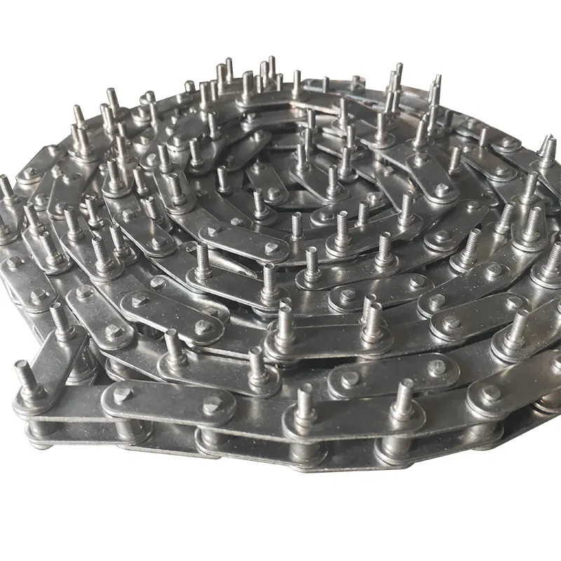
What are the benefits of using a corrosion-resistant material for a transmission chain?
Using a corrosion-resistant material for a transmission chain offers several advantages. Here’s a detailed answer to the question:
Corrosion-resistant materials, such as stainless steel or specialized coatings, provide the following benefits for transmission chains:
1. Enhanced Durability: Corrosion can significantly reduce the lifespan of a transmission chain by causing surface degradation, pitting, or rusting. By using a corrosion-resistant material, the chain’s durability is improved, allowing it to withstand exposure to harsh environments, chemicals, moisture, and temperature variations.
2. Extended Service Life: Corrosion-resistant materials help prevent or minimize the formation of rust or corrosion on the chain’s surface. This extends the chain’s service life, reducing the frequency of replacements and associated downtime and maintenance costs.
3. Reliable Performance: Corrosion can negatively impact the performance of a transmission chain by increasing friction, decreasing flexibility, and impairing the smooth engagement with sprockets or other components. Using a corrosion-resistant material ensures consistent and reliable performance, allowing the chain to operate smoothly and efficiently.
4. Reduced Maintenance: Corrosion-resistant transmission chains require less maintenance compared to chains made from non-corrosion-resistant materials. They are less prone to surface damage, require fewer lubrication intervals, and generally demand less attention to prevent deterioration. This results in reduced maintenance efforts and costs.
5. Suitable for Challenging Environments: Many industries and applications expose transmission chains to corrosive substances, moisture, humidity, or high temperatures. Using a corrosion-resistant material ensures that the chain can perform reliably in these challenging environments, such as marine, chemical processing, food processing, or outdoor applications.
6. Improved Safety: Corrosion can compromise the integrity and strength of a transmission chain, potentially leading to chain failure or unexpected equipment downtime. Utilizing a corrosion-resistant material helps maintain the chain’s structural integrity, reducing the risk of accidents, equipment failures, and associated safety hazards.
It’s important to consider the specific requirements of the application and the level of corrosion resistance needed when selecting a transmission chain material. Factors such as environmental conditions, temperature, exposure to chemicals, and industry standards should be taken into account to ensure optimal performance and longevity of the chain.
What are the advantages of using a lubrication-free transmission chain?
Using a lubrication-free transmission chain offers several benefits. Here’s a detailed answer to the question:
1. Maintenance-free Operation: Lubrication-free transmission chains eliminate the need for regular lubrication and maintenance. This saves time, reduces maintenance costs, and minimizes downtime associated with lubrication tasks.
2. Clean and Environmentally Friendly: Lubrication-free chains operate without the need for external lubricants, which eliminates the risk of oil or grease contamination in the surrounding environment. This is particularly advantageous in applications where cleanliness is crucial, such as in food processing, pharmaceutical, or cleanroom environments.
3. Reduced Friction and Wear: Lubrication-free chains are designed with self-lubricating materials or coatings that offer low friction and excellent wear resistance. These chains are specifically engineered to provide long-lasting performance without the need for external lubrication. The reduced friction and wear contribute to extended chain life and improved efficiency.
4. Enhanced Reliability: Lubrication-free transmission chains provide consistent and reliable performance, as they are not dependent on external lubrication that can deteriorate or deplete over time. They are designed to withstand various operating conditions and maintain their performance even in the absence of lubrication.
5. Wide Range of Applications: Lubrication-free transmission chains are suitable for a wide range of applications across different industries. They are commonly used in industries such as food and beverage, packaging, medical equipment, textile, and electronics, where lubrication may not be feasible or desirable.
6. Improved Cleanliness and Safety: Lubrication-free chains contribute to a cleaner working environment by eliminating the risk of oil or grease leaks. This enhances workplace safety, reduces the potential for slip hazards, and ensures compliance with stringent cleanliness standards.
It’s important to note that lubrication-free chains are designed and manufactured using specialized materials and coatings to provide the necessary self-lubricating properties. It’s essential to choose the appropriate lubrication-free chain based on the specific application requirements and operating conditions.
Are there any industry standards or certifications for transmission chains?
Yes, there are industry standards and certifications that govern the manufacturing, quality, and performance of transmission chains. Here’s a detailed explanation:
1. ANSI/ASME Standards: The American National Standards Institute (ANSI) and the American Society of Mechanical Engineers (ASME) have developed standards for transmission chains, such as ANSI/ASME B29.1 for roller chains and ANSI/ASME B29.3 for pintle chains. These standards define the dimensions, materials, tolerances, and performance requirements for various types of transmission chains.
2. ISO Standards: The International Organization for Standardization (ISO) has also established standards for transmission chains, including ISO 606 for short-pitch precision roller chains and ISO 1275 for short-pitch conveyor chains. These standards ensure global consistency and compatibility in terms of chain dimensions and performance.
3. DIN Standards: In Germany, the Deutsches Institut für Normung (DIN) has developed standards for transmission chains, such as DIN 8187 for roller chains and DIN 8181 for bush chains. These standards are widely used in Europe and define the specifications and requirements for chain design and performance.
4. Certifications: In addition to standards, there are certifications that validate the quality and performance of transmission chains. One notable certification is the ISO 9001:2015, which demonstrates that the manufacturer has implemented a quality management system and meets the specified criteria for consistent product quality.
It is important to note that adherence to these standards and certifications is voluntary but highly recommended. Choosing transmission chains that comply with recognized standards and certifications ensures that they have been manufactured and tested to meet specific criteria for performance, reliability, and durability.
When selecting transmission chains, it is advisable to look for products from reputable manufacturers who prioritize quality and compliance with industry standards. This helps to ensure that the chains you choose will meet the necessary requirements for your application and deliver reliable performance over time.
editor by CX 2023-10-23
China Custom Gearbox Transmission Belt Parts Attachment Products 15 a Series Short Pitch Precision Simplex Roller Chains and Bush Chains for Agriculture
Product Description
A Series Short pitch Precision Simplex Roller Chains & Bush Chains
| ISO/ANSI/ DIN Chain No. |
China Chain No. |
Pitch P mm |
Roller diameter
d1max |
Width between inner plates b1min mm |
Pin diameter
d2max |
Pin length | Inner plate depth h2max mm |
Plate thickness
Tmax |
Tensile strength
Qmin |
Average tensile strength Q0 kN |
Weight per meter q kg/m |
|
| Lmax mm |
Lcmax mm |
|||||||||||
| 15 | *03C | 4.7625 | 2.48 | 2.38 | 1.62 | 6.10 | 6.90 | 4.30 | 0.60 | 1.80/409 | 2.0 | 0.08 |
*Bush chain:d1 in the table indicates the external diameter of the bush
ROLLER CHAIN
Roller chain or bush roller chain is the type of chain drive most commonly used for transmission of mechanical power on many kinds of domestic, industrial and agricultural machinery, including conveyors, wire- and tube-drawing machines, printing presses, cars, motorcycles, and bicycles. It consists of a series of short cylindrical rollers held together by side links. It is driven by a toothed wheel called a sprocket. It is a simple, reliable, and efficient means of power transmission.
CONSTRUCTION OF THE CHAIN
Two different sizes of roller chain, showing construction.
There are 2 types of links alternating in the bush roller chain. The first type is inner links, having 2 inner plates held together by 2 sleeves or bushings CHINAMFG which rotate 2 rollers. Inner links alternate with the second type, the outer links, consisting of 2 outer plates held together by pins passing through the bushings of the inner links. The “bushingless” roller chain is similar in operation though not in construction; instead of separate bushings or sleeves holding the inner plates together, the plate has a tube stamped into it protruding from the hole which serves the same purpose. This has the advantage of removing 1 step in assembly of the chain.
The roller chain design reduces friction compared to simpler designs, resulting in higher efficiency and less wear. The original power transmission chain varieties lacked rollers and bushings, with both the inner and outer plates held by pins which directly contacted the sprocket teeth; however this configuration exhibited extremely rapid wear of both the sprocket teeth, and the plates where they pivoted on the pins. This problem was partially solved by the development of bushed chains, with the pins holding the outer plates passing through bushings or sleeves connecting the inner plates. This distributed the wear over a greater area; however the teeth of the sprockets still wore more rapidly than is desirable, from the sliding friction against the bushings. The addition of rollers surrounding the bushing sleeves of the chain and provided rolling contact with the teeth of the sprockets resulting in excellent resistance to wear of both sprockets and chain as well. There is even very low friction, as long as the chain is sufficiently lubricated. Continuous, clean, lubrication of roller chains is of primary importance for efficient operation as well as correct tensioning.
LUBRICATION
Many driving chains (for example, in factory equipment, or driving a camshaft inside an internal combustion engine) operate in clean environments, and thus the wearing surfaces (that is, the pins and bushings) are safe from precipitation and airborne grit, many even in a sealed environment such as an oil bath. Some roller chains are designed to have o-rings built into the space between the outside link plate and the inside roller link plates. Chain manufacturers began to include this feature in 1971 after the application was invented by Joseph Montano while working for Whitney Chain of Hartford, Connecticut. O-rings were included as a way to improve lubrication to the links of power transmission chains, a service that is vitally important to extending their working life. These rubber fixtures form a barrier that holds factory applied lubricating grease inside the pin and bushing wear areas. Further, the rubber o-rings prevent dirt and other contaminants from entering inside the chain linkages, where such particles would otherwise cause significant wear.[citation needed]
There are also many chains that have to operate in dirty conditions, and for size or operational reasons cannot be sealed. Examples include chains on farm equipment, bicycles, and chain saws. These chains will necessarily have relatively high rates of wear, particularly when the operators are prepared to accept more friction, less efficiency, more noise and more frequent replacement as they neglect lubrication and adjustment.
Many oil-based lubricants attract dirt and other particles, eventually forming an CHINAMFG paste that will compound wear on chains. This problem can be circumvented by use of a “dry” PTFE spray, which forms a solid film after application and repels both particles and moisture.
VARIANTS DESIGN
Layout of a roller chain: 1. Outer plate, 2. Inner plate, 3. Pin, 4. Bushing, 5. Roller
If the chain is not being used for a high wear application (for instance if it is just transmitting motion from a hand-operated lever to a control shaft on a machine, or a sliding door on an oven), then 1 of the simpler types of chain may still be used. Conversely, where extra strength but the smooth drive of a smaller pitch is required, the chain may be “siamesed”; instead of just 2 rows of plates on the outer sides of the chain, there may be 3 (“duplex”), 4 (“triplex”), or more rows of plates running parallel, with bushings and rollers between each adjacent pair, and the same number of rows of teeth running in parallel on the sprockets to match. Timing chains on automotive engines, for example, typically have multiple rows of plates called strands.
Roller chain is made in several sizes, the most common American National Standards Institute (ANSI) standards being 40, 50, 60, and 80. The first digit(s) indicate the pitch of the chain in eighths of an inch, with the last digit being 0 for standard chain, 1 for lightweight chain, and 5 for bushed chain with no rollers. Thus, a chain with half-inch pitch would be a #40 while a #160 sprocket would have teeth spaced 2 inches apart, etc. Metric pitches are expressed in sixteenths of an inch; thus a metric #8 chain (08B-1) would be equivalent to an ANSI #40. Most roller chain is made from plain carbon or alloy steel, but stainless steel is used in food processing machinery or other places where lubrication is a problem, and nylon or brass are occasionally seen for the same reason.
Roller chain is ordinarily hooked up using a master link (also known as a connecting link), which typically has 1 pin held by a horseshoe clip rather than friction fit, allowing it to be inserted or removed with simple tools. Chain with a removable link or pin is also known as cottered chain, which allows the length of the chain to be adjusted. Half links (also known as offsets) are available and are used to increase the length of the chain by a single roller. Riveted roller chain has the master link (also known as a connecting link) “riveted” or mashed on the ends. These pins are made to be durable and are not removable.
USE
An example of 2 ‘ghost’ sprockets tensioning a triplex roller chain system
Roller chains are used in low- to mid-speed drives at around 600 to 800 feet per minute; however, at higher speeds, around 2,000 to 3,000 feet per minute, V-belts are normally used due to wear and noise issues.
A bicycle chain is a form of roller chain. Bicycle chains may have a master link, or may require a chain tool for removal and installation. A similar but larger and thus stronger chain is used on most motorcycles although it is sometimes replaced by either a toothed belt or a shaft drive, which offer lower noise level and fewer maintenance requirements.
The great majority of automobile engines use roller chains to drive the camshaft(s). Very high performance engines often use gear drive, and starting in the early 1960s toothed belts were used by some manufacturers.
Chains are also used in forklifts using hydraulic rams as a pulley to raise and lower the carriage; however, these chains are not considered roller chains, but are classified as lift or leaf chains.
Chainsaw cutting chains superficially resemble roller chains but are more closely related to leaf chains. They are driven by projecting drive links which also serve to locate the chain CHINAMFG the bar.
Sea Harrier FA.2 ZA195 front (cold) vector thrust nozzle – the nozzle is rotated by a chain drive from an air motor
A perhaps unusual use of a pair of motorcycle chains is in the Harrier Jump Jet, where a chain drive from an air motor is used to rotate the movable engine nozzles, allowing them to be pointed downwards for hovering flight, or to the rear for normal CHINAMFG flight, a system known as Thrust vectoring.
WEAR
The effect of wear on a roller chain is to increase the pitch (spacing of the links), causing the chain to grow longer. Note that this is due to wear at the pivoting pins and bushes, not from actual stretching of the metal (as does happen to some flexible steel components such as the hand-brake cable of a motor vehicle).
With modern chains it is unusual for a chain (other than that of a bicycle) to wear until it breaks, since a worn chain leads to the rapid onset of wear on the teeth of the sprockets, with ultimate failure being the loss of all the teeth on the sprocket. The sprockets (in particular the smaller of the two) suffer a grinding motion that puts a characteristic hook shape into the driven face of the teeth. (This effect is made worse by a chain improperly tensioned, but is unavoidable no matter what care is taken). The worn teeth (and chain) no longer provides smooth transmission of power and this may become evident from the noise, the vibration or (in car engines using a timing chain) the variation in ignition timing seen with a timing light. Both sprockets and chain should be replaced in these cases, since a new chain on worn sprockets will not last long. However, in less severe cases it may be possible to save the larger of the 2 sprockets, since it is always the smaller 1 that suffers the most wear. Only in very light-weight applications such as a bicycle, or in extreme cases of improper tension, will the chain normally jump off the sprockets.
The lengthening due to wear of a chain is calculated by the following formula:
M = the length of a number of links measured
S = the number of links measured
P = Pitch
In industry, it is usual to monitor the movement of the chain tensioner (whether manual or automatic) or the exact length of a drive chain (one rule of thumb is to replace a roller chain which has elongated 3% on an adjustable drive or 1.5% on a fixed-center drive). A simpler method, particularly suitable for the cycle or motorcycle user, is to attempt to pull the chain away from the larger of the 2 sprockets, whilst ensuring the chain is taut. Any significant movement (e.g. making it possible to see through a gap) probably indicates a chain worn up to and beyond the limit. Sprocket damage will result if the problem is ignored. Sprocket wear cancels this effect, and may mask chain wear.
CHAIN STRENGTH
The most common measure of roller chain’s strength is tensile strength. Tensile strength represents how much load a chain can withstand under a one-time load before breaking. Just as important as tensile strength is a chain’s fatigue strength. The critical factors in a chain’s fatigue strength is the quality of steel used to manufacture the chain, the heat treatment of the chain components, the quality of the pitch hole fabrication of the linkplates, and the type of shot plus the intensity of shot peen coverage on the linkplates. Other factors can include the thickness of the linkplates and the design (contour) of the linkplates. The rule of thumb for roller chain operating on a continuous drive is for the chain load to not exceed a mere 1/6 or 1/9 of the chain’s tensile strength, depending on the type of master links used (press-fit vs. slip-fit)[citation needed]. Roller chains operating on a continuous drive beyond these thresholds can and typically do fail prematurely via linkplate fatigue failure.
The standard minimum ultimate strength of the ANSI 29.1 steel chain is 12,500 x (pitch, in inches)2. X-ring and O-Ring chains greatly decrease wear by means of internal lubricants, increasing chain life. The internal lubrication is inserted by means of a vacuum when riveting the chain together.
CHAIN STHangZhouRDS
Standards organizations (such as ANSI and ISO) maintain standards for design, dimensions, and interchangeability of transmission chains. For example, the following Table shows data from ANSI standard B29.1-2011 (Precision Power Transmission Roller Chains, Attachments, and Sprockets) developed by the American Society of Mechanical Engineers (ASME). See the references[8][9][10] for additional information.
ASME/ANSI B29.1-2011 Roller Chain Standard SizesSizePitchMaximum Roller DiameterMinimum Ultimate Tensile StrengthMeasuring Load25
| ASME/ANSI B29.1-2011 Roller Chain Standard Sizes | ||||
| Size | Pitch | Maximum Roller Diameter | Minimum Ultimate Tensile Strength | Measuring Load |
|---|---|---|---|---|
| 25 | 0.250 in (6.35 mm) | 0.130 in (3.30 mm) | 780 lb (350 kg) | 18 lb (8.2 kg) |
| 35 | 0.375 in (9.53 mm) | 0.200 in (5.08 mm) | 1,760 lb (800 kg) | 18 lb (8.2 kg) |
| 41 | 0.500 in (12.70 mm) | 0.306 in (7.77 mm) | 1,500 lb (680 kg) | 18 lb (8.2 kg) |
| 40 | 0.500 in (12.70 mm) | 0.312 in (7.92 mm) | 3,125 lb (1,417 kg) | 31 lb (14 kg) |
| 50 | 0.625 in (15.88 mm) | 0.400 in (10.16 mm) | 4,880 lb (2,210 kg) | 49 lb (22 kg) |
| 60 | 0.750 in (19.05 mm) | 0.469 in (11.91 mm) | 7,030 lb (3,190 kg) | 70 lb (32 kg) |
| 80 | 1.000 in (25.40 mm) | 0.625 in (15.88 mm) | 12,500 lb (5,700 kg) | 125 lb (57 kg) |
| 100 | 1.250 in (31.75 mm) | 0.750 in (19.05 mm) | 19,531 lb (8,859 kg) | 195 lb (88 kg) |
| 120 | 1.500 in (38.10 mm) | 0.875 in (22.23 mm) | 28,125 lb (12,757 kg) | 281 lb (127 kg) |
| 140 | 1.750 in (44.45 mm) | 1.000 in (25.40 mm) | 38,280 lb (17,360 kg) | 383 lb (174 kg) |
| 160 | 2.000 in (50.80 mm) | 1.125 in (28.58 mm) | 50,000 lb (23,000 kg) | 500 lb (230 kg) |
| 180 | 2.250 in (57.15 mm) | 1.460 in (37.08 mm) | 63,280 lb (28,700 kg) | 633 lb (287 kg) |
| 200 | 2.500 in (63.50 mm) | 1.562 in (39.67 mm) | 78,175 lb (35,460 kg) | 781 lb (354 kg) |
| 240 | 3.000 in (76.20 mm) | 1.875 in (47.63 mm) | 112,500 lb (51,000 kg) | 1,000 lb (450 kg |
For mnemonic purposes, below is another presentation of key dimensions from the same standard, expressed in fractions of an inch (which was part of the thinking behind the choice of preferred numbers in the ANSI standard):
| Pitch (inches) | Pitch expressed in eighths |
ANSI standard chain number |
Width (inches) |
|---|---|---|---|
| 1⁄4 | 2⁄8 | 25 | 1⁄8 |
| 3⁄8 | 3⁄8 | 35 | 3⁄16 |
| 1⁄2 | 4⁄8 | 41 | 1⁄4 |
| 1⁄2 | 4⁄8 | 40 | 5⁄16 |
| 5⁄8 | 5⁄8 | 50 | 3⁄8 |
| 3⁄4 | 6⁄8 | 60 | 1⁄2 |
| 1 | 8⁄8 | 80 | 5⁄8 |
Notes:
1. The pitch is the distance between roller centers. The width is the distance between the link plates (i.e. slightly more than the roller width to allow for clearance).
2. The right-hand digit of the standard denotes 0 = normal chain, 1 = lightweight chain, 5 = rollerless bushing chain.
3. The left-hand digit denotes the number of eighths of an inch that make up the pitch.
4. An “H” following the standard number denotes heavyweight chain. A hyphenated number following the standard number denotes double-strand (2), triple-strand (3), and so on. Thus 60H-3 denotes number 60 heavyweight triple-strand chain.
A typical bicycle chain (for derailleur gears) uses narrow 1⁄2-inch-pitch chain. The width of the chain is variable, and does not affect the load capacity. The more sprockets at the rear wheel (historically 3-6, nowadays 7-12 sprockets), the narrower the chain. Chains are sold according to the number of speeds they are designed to work with, for example, “10 speed chain”. Hub gear or single speed bicycles use 1/2″ x 1/8″ chains, where 1/8″ refers to the maximum thickness of a sprocket that can be used with the chain.
Typically chains with parallel shaped links have an even number of links, with each narrow link followed by a broad one. Chains built up with a uniform type of link, narrow at 1 and broad at the other end, can be made with an odd number of links, which can be an advantage to adapt to a special chainwheel-distance; on the other side such a chain tends to be not so strong.
Roller chains made using ISO standard are sometimes called as isochains.
WHY CHOOSE US
1. Reliable Quality Assurance System
2. Cutting-Edge Computer-Controlled CNC Machines
3. Bespoke Solutions from Highly Experienced Specialists
4. Customization and OEM Available for Specific Application
5. Extensive Inventory of Spare Parts and Accessories
6. Well-Developed CHINAMFG Marketing Network
7. Efficient After-Sale Service System
The 219 sets of advanced automatic production equipment provide guarantees for high product quality. The 167 engineers and technicians with senior professional titles can design and develop products to meet the exact demands of customers, and OEM customizations are also available with us. Our sound global service network can provide customers with timely after-sales technical services.
We are not just a manufacturer and supplier, but also an industry consultant. We work pro-actively with you to offer expert advice and product recommendations in order to end up with a most cost effective product available for your specific application. The clients we serve CHINAMFG range from end users to distributors and OEMs. Our OEM replacements can be substituted wherever necessary and suitable for both repair and new assemblies.
|
Shipping Cost:
Estimated freight per unit. |
To be negotiated |
|---|
| Standard or Nonstandard: | Standard |
|---|---|
| Application: | Textile Machinery, Garment Machinery, Conveyer Equipment, Packaging Machinery, Electric Cars, Motorcycle, Food Machinery, Marine, Mining Equipment, Agricultural Machinery, Car |
| Surface Treatment: | Polishing |
| Samples: |
US$ 3/Meter
1 Meter(Min.Order) | Order Sample |
|---|
| Customization: |
Available
| Customized Request |
|---|
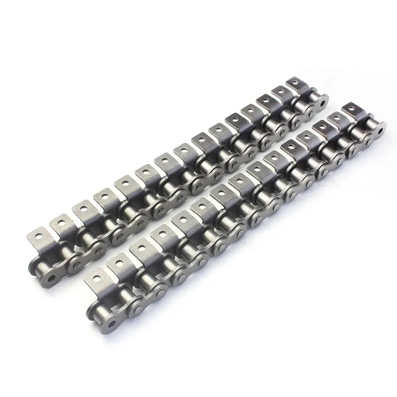
How does the elongation of a transmission chain affect its lifespan?
Transmission chains are subject to gradual elongation over time as a result of wear and fatigue. The elongation of a transmission chain refers to the increase in its length due to the stretching of the chain’s components. Here’s a detailed explanation of how elongation affects the lifespan of a transmission chain:
1. Increased Slack: As a transmission chain elongates, it develops more slack between the chain links. The increased slack reduces the chain’s tension and can negatively impact its performance. Excessive slack can lead to chain skipping, misalignment, and reduced power transmission efficiency. This can cause vibrations, noise, and accelerated wear on the chain and sprockets.
2. Accelerated Wear: Elongation puts additional stress on the chain’s pins, bushings, and rollers. The increased tension and movement between the chain’s components lead to accelerated wear and fatigue. This can result in chain elongation becoming a self-perpetuating problem, as the worn components further contribute to elongation and reduced performance.
3. Decreased Load Capacity: Elongation reduces the effective pitch length of the transmission chain, resulting in decreased load-carrying capacity. The reduced load capacity can limit the chain’s ability to handle heavy loads or transmit power effectively. This can lead to premature failure or damage to the chain and associated machinery.
4. Increased Maintenance Requirements: Elongated transmission chains require more frequent maintenance and adjustment to maintain proper tension and performance. Regular monitoring and adjustment of chain tension are necessary to minimize wear, prevent excessive elongation, and ensure optimal power transmission. Failure to address elongation promptly can lead to more severe damage to the chain and other components, resulting in costly repairs and downtime.
5. Reduced Service Life: The elongation of a transmission chain directly affects its service life. As the chain elongates, its performance, efficiency, and load-carrying capacity gradually deteriorate. The rate of elongation depends on various factors such as chain quality, operating conditions, lubrication, and maintenance practices. Over time, if elongation is not addressed, the chain may become unable to perform its intended function effectively, leading to chain failure and the need for replacement.
To mitigate the negative effects of elongation and extend the lifespan of a transmission chain, regular maintenance, including proper lubrication and tension adjustment, is crucial. Periodic inspections for signs of wear, elongation, and fatigue should be conducted to identify potential issues early and take appropriate corrective measures. Additionally, selecting high-quality chains and following manufacturer recommendations for installation, operation, and maintenance can help minimize elongation and maximize the chain’s lifespan.
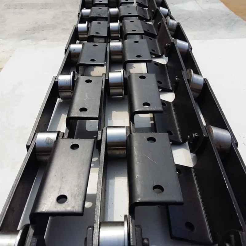
Can transmission chains be used in high-torque applications?
Yes, transmission chains are commonly used in high-torque applications due to their ability to transmit power efficiently. Here’s a detailed answer to the question:
1. Robust Power Transmission: Transmission chains are designed to handle significant amounts of power transmission, including high-torque applications. They are capable of transferring torque from the driving source to the driven components effectively.
2. Load Capacity: Transmission chains are engineered to withstand heavy loads and high levels of torque. They are designed with appropriate material strength, chain pitch, and components to handle the specific torque requirements of the application.
3. Diverse Applications: Transmission chains are utilized in various high-torque applications across industries such as automotive, construction, mining, agriculture, and manufacturing. They are commonly used in power transmission systems, machinery, equipment, conveyors, and other mechanisms that require efficient torque transfer.
4. Compatibility with Sprockets: Transmission chains work in conjunction with sprockets, which are designed to engage with the chain links and transfer torque. The design and selection of appropriate sprockets ensure smooth and reliable torque transmission in high-torque applications.
5. Strength and Durability: Transmission chains are manufactured using high-strength materials such as alloy steel, stainless steel, or heat-treated steels to provide the necessary strength and durability required for high-torque operations. These materials can withstand the forces generated by high levels of torque without premature wear or failure.
6. Proper Lubrication and Maintenance: To ensure optimal performance in high-torque applications, it is essential to maintain proper lubrication and perform regular maintenance on the transmission chain. Adequate lubrication reduces friction, heat generation, and wear, thereby prolonging the chain’s lifespan and preserving its torque transmission capabilities.
It’s important to consult with industry experts or manufacturers to select the appropriate transmission chain and ensure it meets the specific torque requirements of the application. Additionally, following recommended installation and maintenance practices will help maximize the performance and longevity of the transmission chain in high-torque applications.

What are the common industries or applications that use transmission chains?
Transmission chains are widely used in various industries and applications where the efficient transfer of power and motion is required. Here are some common industries and applications that rely on transmission chains:
- Automotive: Transmission chains are used in automobile engines and drivetrains to transfer power from the engine to the wheels.
- Agriculture: Transmission chains are utilized in agricultural machinery such as tractors, combines, and harvesters for power transmission in various applications like conveyor systems and agricultural equipment.
- Industrial Manufacturing: Transmission chains are found in a wide range of industrial machinery, including conveyors, material handling systems, packaging equipment, printing presses, and machine tools.
- Mining and Construction: Transmission chains are used in heavy machinery, such as excavators, bulldozers, and mining equipment, to transmit power for digging, lifting, and other operations.
- Food and Beverage: Transmission chains are employed in food processing equipment, bottling plants, and conveyor systems to move products along production lines.
- Textile: Transmission chains are utilized in textile manufacturing machinery, such as looms and spinning machines, for power transmission during the weaving and spinning processes.
- Energy and Utilities: Transmission chains are used in power generation plants, wind turbines, and other renewable energy systems for transmitting power from the source to the electrical grid.
- Material Handling: Transmission chains are commonly used in material handling equipment, including forklifts, palletizers, and automated storage systems, to transport and handle goods in warehouses and distribution centers.
- Marine: Transmission chains find applications in marine vessels, such as ship propulsion systems, anchor handling equipment, and winches for cargo handling.
These are just a few examples, and transmission chains are also utilized in various other industries and applications where reliable power transmission is essential. The specific design and characteristics of the transmission chains may vary based on the requirements of each industry and application.
editor by CX 2023-09-19
China factory Short Pitch Precision Roller Chains and Bush Chains Customized Chain Sprocket 80b (16B) for Agricultural Machinery by China Manufacturer
Product Description
SPROCKET 1” X 17.02mm 16B SERIES SPROCKETS
| For Chain Acc.to DIN8187 ISO/R 606 | |||||
| Tooth Radius r3 | 26.0mm | ||||
| Radius Width C | 2.5mm | ||||
| Tooth Width b1 | 15.8mm | ||||
| Tooth Width B1 | 16.2mm | ||||
| Tooth Width B2 | 47.7mm | ||||
| Tooth Width B3 | 79.6mm | ||||
| 16B SERIES ROLLER CHAINS | |||||
| Pitch | 25.4 mm | ||||
| Internal Width | 17.02 mm | ||||
| Roller Diameter | 15.88mm | ||||
Products Show
| Z | de | dp | SIMPLEX | DUPLEX | TRIPLEX | ||||||
| dm | D1 | A | dm | D2 | A | dm | D2 | A | |||
| 8 | 77.0 | 66.37 | 42 | 16 | 35 | 42 | 16 | 65 | 42 | 20 | 95 |
| 9 | 85.0 | 74.27 | 50 | 16 | 35 | 50 | 16 | 65 | 50 | 20 | 95 |
| 10 | 93.0 | 82.19 | 55 | 16 | 35 | 56 | 16 | 65 | 56 | 20 | 95 |
| 11 | 105.1 | 90.14 | 61 | 16 | 40 | 64 | 20 | 70 | 64 | 25 | 100 |
| 12 | 109.0 | 98.14 | 69 | 16 | 40 | 72 | 20 | 70 | 72 | 25 | 100 |
| 13 | 117.0 | 106.12 | 78 | 16 | 40 | 80 | 20 | 70 | 80 | 25 | 100 |
| 14 | 125.0 | 114.15 | 84 | 16 | 40 | 88 | 20 | 70 | 88 | 25 | 100 |
| 15 | 133.0 | 122.17 | 92 | 16 | 40 | 96 | 20 | 70 | 96 | 25 | 100 |
| 16 | 141.0 | 130.20 | 100 | 20 | 45 | 104 | 20 | 70 | 104 | 25 | 100 |
| 17 | 149.0 | 138.22 | 100 | 20 | 45 | 112 | 20 | 70 | 112 | 25 | 100 |
| 18 | 157.0 | 146.28 | 100 | 20 | 45 | 120 | 20 | 70 | 120 | 25 | 100 |
| 19 | 165.2 | 154.33 | 100 | 20 | 45 | 128 | 20 | 70 | 128 | 25 | 100 |
| 20 | 173.2 | 162.38 | 100 | 20 | 45 | 130 | 20 | 70 | 130 | 25 | 100 |
| 21 | 181.2 | 170.43 | 110 | 20 | 50 | 130 | 25 | 70 | *130 | 25 | 100 |
| 22 | 189.3 | 178.48 | 110 | 20 | 50 | *130 | 25 | 70 | *130 | 25 | 100 |
| 23 | 197.5 | 186.53 | 110 | 20 | 50 | *130 | 25 | 70 | *130 | 25 | 100 |
| 24 | 205.5 | 194.59 | 110 | 20 | 50 | *130 | 25 | 70 | *130 | 25 | 100 |
| 25 | 213.5 | 202.66 | 110 | 20 | 50 | *130 | 25 | 70 | *130 | 25 | 100 |
| 26 | 221.6 | 210.72 | 120 | 20 | 50 | *130 | 25 | 70 | *130 | 30 | 100 |
| 27 | 229.6 | 218.79 | 120 | 20 | 50 | *130 | 25 | 70 | *130 | 30 | 100 |
| 28 | 237.7 | 226.85 | 120 | 20 | 50 | *130 | 25 | 70 | *130 | 30 | 100 |
| 29 | 245.8 | 234.92 | 120 | 20 | 50 | *130 | 25 | 70 | *130 | 30 | 100 |
| 30 | 254.0 | 243.00 | 120 | 20 | 50 | *130 | 25 | 70 | *130 | 30 | 100 |
| 31 | 262.0 | 251.08 | *120 | 25 | 50 | *140 | 25 | 70 | *140 | 30 | 100 |
| 32 | 270.0 | 259.13 | *120 | 25 | 50 | *140 | 25 | 70 | *140 | 30 | 100 |
| 33 | 278.5 | 267.21 | *120 | 25 | 50 | *140 | 25 | 70 | *140 | 30 | 100 |
| 34 | 287.0 | 275.28 | *120 | 25 | 50 | *140 | 25 | 70 | *140 | 30 | 100 |
| 35 | 296.2 | 283.36 | *120 | 25 | 50 | *140 | 25 | 70 | *140 | 30 | 100 |
| 36 | 304.6 | 291.44 | *120 | 25 | 50 | *140 | 25 | 70 | *140 | 30 | 100 |
| 37 | 312.6 | 299.51 | *120 | 25 | 50 | *140 | 25 | 70 | *140 | 30 | 100 |
| 38 | 320.7 | 307.59 | *120 | 25 | 50 | *140 | 25 | 70 | *140 | 30 | 100 |
| 39 | 328.8 | 315.67 | *120 | 25 | 50 | *140 | 25 | 70 | *140 | 30 | 100 |
| 40 | 336.9 | 323.75 | *120 | 25 | 50 | *140 | 25 | 70 | *140 | 30 | 100 |
| 41 | 345.0 | 331.81 | *125 | 25 | 68 | *140 | 25 | 70 | *160 | 30 | 100 |
| 42 | 353.0 | 339.89 | *125 | 25 | 68 | *140 | 25 | 70 | *160 | 30 | 100 |
| 43 | 361.1 | 347.97 | *125 | 25 | 68 | *140 | 25 | 70 | *160 | 30 | 100 |
| 44 | 369.1 | 356.05 | *125 | 25 | 68 | *140 | 25 | 70 | *160 | 30 | 100 |
| 45 | 377.1 | 364.12 | *125 | 25 | 68 | *140 | 25 | 70 | *160 | 30 | 100 |
| 46 | 385.2 | 372.20 | *125 | 25 | 68 | *140 | 25 | 70 | *160 | 30 | 100 |
| 47 | 393.2 | 380.28 | *125 | 25 | 68 | *140 | 25 | 70 | *160 | 30 | 100 |
| 48 | 401.3 | 388.36 | *125 | 25 | 68 | *140 | 25 | 70 | *160 | 30 | 100 |
| 49 | 409.3 | 396.44 | *125 | 25 | 68 | *140 | 25 | 70 | *160 | 30 | 100 |
| 50 | 417.4 | 404.52 | *125 | 25 | 68 | *140 | 25 | 70 | *160 | 30 | 100 |
| 51 | 425.5 | 412.60 | *125 | 25 | 68 | *150 | 25 | 85 | *180 | 30 | 110 |
| 52 | 433.6 | 420.68 | *125 | 25 | 68 | *150 | 25 | 85 | *180 | 30 | 110 |
| 53 | 441.7 | 428.76 | *125 | 25 | 68 | *150 | 25 | 85 | *180 | 30 | 110 |
| 54 | 448.3 | 436.84 | *125 | 25 | 68 | *150 | 25 | 85 | *180 | 30 | 110 |
| 55 | 457.9 | 444.92 | *125 | 25 | 68 | *150 | 25 | 85 | *180 | 30 | 110 |
| 56 | 466.0 | 453.01 | *125 | 25 | 68 | *150 | 25 | 85 | *180 | 30 | 110 |
| 57 | 474.0 | 461.08 | *125 | 25 | 68 | *150 | 25 | 85 | *180 | 30 | 110 |
| 58 | 482.1 | 469.16 | *133 | 25 | 68 | *150 | 25 | 85 | *180 | 30 | 110 |
| 59 | 490.2 | 477.24 | *133 | 25 | 68 | *150 | 25 | 85 | *180 | 30 | 110 |
| 60 | 498.3 | 485.23 | *133 | 25 | 68 | *150 | 25 | 85 | *180 | 30 | 110 |
| 62 | 514.5 | 501.49 | *133 | 25 | 68 | *150 | 25 | 85 | *180 | 30 | 110 |
| 64 | 530.7 | 517.65 | *140 | 25 | 68 | *160 | 25 | 90 | *180 | 30 | 110 |
| 65 | 538.8 | 525.73 | *140 | 25 | 68 | *160 | 25 | 90 | *180 | 30 | 110 |
| 66 | 546.8 | 533.80 | *140 | 25 | 68 | *160 | 25 | 90 | *180 | 30 | 110 |
| 68 | 562.9 | 549.98 | *140 | 25 | 68 | *160 | 25 | 90 | *180 | 30 | 110 |
| 70 | 579.2 | 566.15 | *140 | 25 | 68 | *160 | 25 | 90 | *180 | 30 | 110 |
| 72 | 595.4 | 582.31 | *140 | 25 | 68 | *160 | 25 | 90 | *180 | 30 | 110 |
| 75 | 619.7 | 606.56 | *140 | 25 | 68 | *160 | 25 | 90 | *180 | 30 | 110 |
| 76 | 627.0 | 614.64 | *140 | 25 | 68 | *160 | 25 | 90 | *180 | 30 | 110 |
| 78 | 643.3 | 630.81 | *140 | 25 | 68 | *160 | 25 | 90 | *180 | 30 | 110 |
| 80 | 660.0 | 646.97 | *140 | 25 | 68 | *160 | 25 | 90 | *180 | 30 | 110 |
| 85 | 699.9 | 687.39 | *140 | 25 | 78 | *160 | 25 | 90 | *180 | 30 | 110 |
| 90 | 740.3 | 727.80 | *140 | 25 | 78 | *160 | 25 | 90 | *180 | 30 | 110 |
| 95 | 781.1 | 768.22 | *140 | 25 | 78 | *160 | 25 | 90 | *180 | 30 | 110 |
| 100 | 821.1 | 808.64 | *140 | 25 | 78 | *160 | 25 | 90 | *180 | 30 | 110 |
| 110 | 902.0 | 889.48 | *140 | 25 | 78 | *160 | 25 | 90 | *180 | 30 | 110 |
| 114 | 934.3 | 921.81 | *140 | 25 | 78 | *160 | 25 | 90 | *180 | 30 | 110 |
| 120 | 982.8 | 970.32 | *140 | 25 | 78 | *160 | 25 | 90 | *180 | 30 | 110 |
| 125 | 1571.3 | 1571.73 | *140 | 25 | 78 | *160 | 25 | 90 | *180 | 30 | 110 |
Notice: *welding hub
BASIC INFO.
| Product name | DIN ISO Standard Sprocket for Roller Chain |
| Materials Available | 1. Stainless Steel: SS304, SS316, etc |
| 2. Alloy Steel: C45, 45Mn, 42CrMo, 20CrMo, etc | |
| 3. OEM according to your request | |
| Surface Treatment | Heat treatment, Quenching treatment, High frequency normalizing treatment, Polishing, Electrophoresis paint processing, Anodic oxidation treatment, etc |
| Characteristic | Fire Resistant, Oil Resistant, Heat Resistant, CZPT resistance, Oxidative resistance, Corrosion resistance, etc |
| Design criterion | ISO DIN ANSI & Customer Drawings |
| Size | Customer Drawings & ISO standard |
| Application | Industrial transmission equipment |
| Package | Wooden Case / Container and pallet, or made-to-order |
| Certificate | ISO9001: 2008 |
| Advantage | Quality first, Service first, Competitive price, Fast delivery |
| Delivery Time | 20 days for samples. 45 days for official order. |
INSTALLATION AND USING
The chain wheel, as a drive or deflection for chains, has pockets to hold the chain links with a D-profile cross section with flat side surfaces parallel to the centre plane of the chain links, and outer surfaces at right angles to the chain link centre plane. The chain links are pressed firmly against the outer surfaces and each of the side surfaces by the angled laying surfaces at the base of the pockets, and also the support surfaces of the wheel body together with the end sides of the webs formed by the leading and trailing walls of the pocket.
NOTICE
When fitting new chain spoket it is very important that a new chain is fitted at the same time, and vice versa. Using an old chain with new sprockets, or a new chain with old sprockets will cause rapid wear.
It is important if you are installing the chainwheels yourself to have the factory service manual specific to your model. Our chainwheels are made to be a direct replacement for your OEM chainwheels and as such, the installation should be performed according to your models service manual.
During use a chain will stretch (i.e. the pins will wear causing extension of the chain). Using a chain which has been stretched more than the above maximum allowance causes the chain to ride up the teeth of the sprocket. This causes damage to the tips of the chainwheels teeth, as the force transmitted by the chain is transmitted entirely through the top of the tooth, rather than the whole tooth. This results in severe wearing of the chainwheel.
FOR CHAIN STHangZhouRDS
Standards organizations (such as ANSI and ISO) maintain standards for design, dimensions, and interchangeability of transmission chains. For example, the following Table shows data from ANSI standard B29.1-2011 (Precision Power Transmission Roller Chains, Attachments, and Sprockets) developed by the American Society of Mechanical Engineers (ASME). See the references[8][9][10] for additional information.
ASME/ANSI B29.1-2011 Roller Chain Standard SizesSizePitchMaximum Roller DiameterMinimum Ultimate Tensile StrengthMeasuring Load25
| ASME/ANSI B29.1-2011 Roller Chain Standard Sizes | ||||
| Size | Pitch | Maximum Roller Diameter | Minimum Ultimate Tensile Strength | Measuring Load |
|---|---|---|---|---|
| 25 | 0.250 in (6.35 mm) | 0.130 in (3.30 mm) | 780 lb (350 kg) | 18 lb (8.2 kg) |
| 35 | 0.375 in (9.53 mm) | 0.200 in (5.08 mm) | 1,760 lb (800 kg) | 18 lb (8.2 kg) |
| 41 | 0.500 in (12.70 mm) | 0.306 in (7.77 mm) | 1,500 lb (680 kg) | 18 lb (8.2 kg) |
| 40 | 0.500 in (12.70 mm) | 0.312 in (7.92 mm) | 3,125 lb (1,417 kg) | 31 lb (14 kg) |
| 50 | 0.625 in (15.88 mm) | 0.400 in (10.16 mm) | 4,880 lb (2,210 kg) | 49 lb (22 kg) |
| 60 | 0.750 in (19.05 mm) | 0.469 in (11.91 mm) | 7,030 lb (3,190 kg) | 70 lb (32 kg) |
| 80 | 1.000 in (25.40 mm) | 0.625 in (15.88 mm) | 12,500 lb (5,700 kg) | 125 lb (57 kg) |
| 100 | 1.250 in (31.75 mm) | 0.750 in (19.05 mm) | 19,531 lb (8,859 kg) | 195 lb (88 kg) |
| 120 | 1.500 in (38.10 mm) | 0.875 in (22.23 mm) | 28,125 lb (12,757 kg) | 281 lb (127 kg) |
| 140 | 1.750 in (44.45 mm) | 1.000 in (25.40 mm) | 38,280 lb (17,360 kg) | 383 lb (174 kg) |
| 160 | 2.000 in (50.80 mm) | 1.125 in (28.58 mm) | 50,000 lb (23,000 kg) | 500 lb (230 kg) |
| 180 | 2.250 in (57.15 mm) | 1.460 in (37.08 mm) | 63,280 lb (28,700 kg) | 633 lb (287 kg) |
| 200 | 2.500 in (63.50 mm) | 1.562 in (39.67 mm) | 78,175 lb (35,460 kg) | 781 lb (354 kg) |
| 240 | 3.000 in (76.20 mm) | 1.875 in (47.63 mm) | 112,500 lb (51,000 kg) | 1,000 lb (450 kg |
For mnemonic purposes, below is another presentation of key dimensions from the same standard, expressed in fractions of an inch (which was part of the thinking behind the choice of preferred numbers in the ANSI standard):
| Pitch (inches) | Pitch expressed in eighths |
ANSI standard chain number |
Width (inches) |
|---|---|---|---|
| 1⁄4 | 2⁄8 | 25 | 1⁄8 |
| 3⁄8 | 3⁄8 | 35 | 3⁄16 |
| 1⁄2 | 4⁄8 | 41 | 1⁄4 |
| 1⁄2 | 4⁄8 | 40 | 5⁄16 |
| 5⁄8 | 5⁄8 | 50 | 3⁄8 |
| 3⁄4 | 6⁄8 | 60 | 1⁄2 |
| 1 | 8⁄8 | 80 | 5⁄8 |
Notes:
1. The pitch is the distance between roller centers. The width is the distance between the link plates (i.e. slightly more than the roller width to allow for clearance).
2. The right-hand digit of the standard denotes 0 = normal chain, 1 = lightweight chain, 5 = rollerless bushing chain.
3. The left-hand digit denotes the number of eighths of an inch that make up the pitch.
4. An “H” following the standard number denotes heavyweight chain. A hyphenated number following the standard number denotes double-strand (2), triple-strand (3), and so on. Thus 60H-3 denotes number 60 heavyweight triple-strand chain.
A typical bicycle chain (for derailleur gears) uses narrow 1⁄2-inch-pitch chain. The width of the chain is variable, and does not affect the load capacity. The more sprockets at the rear wheel (historically 3-6, nowadays 7-12 sprockets), the narrower the chain. Chains are sold according to the number of speeds they are designed to work with, for example, “10 speed chain”. Hub gear or single speed bicycles use 1/2″ x 1/8″ chains, where 1/8″ refers to the maximum thickness of a sprocket that can be used with the chain.
Typically chains with parallel shaped links have an even number of links, with each narrow link followed by a broad one. Chains built up with a uniform type of link, narrow at 1 and broad at the other end, can be made with an odd number of links, which can be an advantage to adapt to a special chainwheel-distance; on the other side such a chain tends to be not so strong.
Roller chains made using ISO standard are sometimes called as isochains.
WHY CHOOSE US
1. Reliable Quality Assurance System
2. Cutting-Edge Computer-Controlled CNC Machines
3. Bespoke Solutions from Highly Experienced Specialists
4. Customization and OEM Available for Specific Application
5. Extensive Inventory of Spare Parts and Accessories
6. Well-Developed CZPT Marketing Network
7. Efficient After-Sale Service System
The 219 sets of advanced automatic production equipment provide guarantees for high product quality. The 167 engineers and technicians with senior professional titles can design and develop products to meet the exact demands of customers, and OEM customizations are also available with us. Our sound global service network can provide customers with timely after-sales technical services.
We are not just a manufacturer and supplier, but also an industry consultant. We work pro-actively with you to offer expert advice and product recommendations in order to end up with a most cost effective product available for your specific application. The clients we serve CZPT range from end users to distributors and OEMs. Our OEM replacements can be substituted wherever necessary and suitable for both repair and new assemblies.
Q:Why choose us ?
A. we are a manufacturer, we have manufactured Chain and Sprocket for over 20 years .
B. Reliable Quality Assurance System;
C. Cutting-Edge Computer-Controlled CNC Machines;
D. Bespoke Solutions from Highly Experienced Specialists;
E. Customization and OEM Available for Specific Application;
F. Extensive Inventory of Spare Parts and Accessories;
G. Well-Developed CZPT Marketing Network;
H. Efficient After-Sale Service System
Q. what is your payment term?
A: 30% TT deposit, 70% balance T/T before shipping.
Q:Can we print our logo on your products?
A: yes, we offer OEM/ODM service, we support the customized logo, size, package,etc.
Q: Can you make chains according to my CAD drawings?
A: Yes. Besides the regular standard chains, we produce non-standard and custom-design products to meet the specific technical requirements. In reality, a sizable portion of our production capacity is assigned to make non-standard products.
Q: what is your main market?
A: North America, South America, Eastern Europe, Western Europe, Southeast Asia, Africa, Oceania, Mid East, Eastern Asia,
Q: Can I get samples from your factory?
A: Yes, Samples can be provided.
Q: If products have some quality problem, how would you deal with?
A: We will responsible for all the quality problems.
|
Shipping Cost:
Estimated freight per unit. |
To be negotiated |
|---|
| Standard Or Nonstandard: | Nonstandard |
|---|---|
| Application: | Motor, Electric Cars, Motorcycle, Machinery, Marine, Toy, Agricultural Machinery, Car, Motor, Electric Cars, Motorcycle, Machinery |
| Hardness: | Hardened Tooth Surface |
| Samples: |
US$ 0/Piece
1 Piece(Min.Order) | Order Sample |
|---|
| Customization: |
Available
| Customized Request |
|---|
Compatibility of Chain Sprockets with Wheels
In general, chain sprockets are designed to work with specific types of wheels, and there are certain requirements for ensuring proper compatibility:
- Chain Size and Pitch: The chain sprocket must match the size and pitch of the chain it is intended to work with. For example, if you have a roller chain with a pitch of 0.625 inches, you need a sprocket with the same pitch to ensure a proper fit.
- Number of Teeth: The number of teeth on the sprocket should be compatible with the number of chain links. The chain should mesh smoothly with the sprocket without any binding or skipping.
- Tooth Profile: The tooth profile of the sprocket should match the shape of the chain’s rollers to ensure smooth engagement and minimize wear.
- Shaft Size: The center hole (bore) of the sprocket should match the diameter of the shaft it will be mounted on. Using the correct shaft size ensures a secure fit and prevents wobbling.
- Hub Configuration: Some sprockets have hubs, which are extensions on either side of the sprocket. The hub’s length and configuration should match the requirements of the specific application.
- Material and Strength: Consider the material and strength of the sprocket based on the application’s load and environmental conditions. Heavy-duty applications may require sprockets made of robust materials to withstand the forces and stresses.
It’s crucial to follow the manufacturer’s specifications and guidelines when selecting a chain sprocket for a particular wheel. Mixing incompatible sprockets and wheels can result in premature wear, inefficiencies, and potential safety hazards. If you are unsure about the compatibility, consult with the manufacturer or a knowledgeable expert to ensure you choose the right sprocket for your specific application.
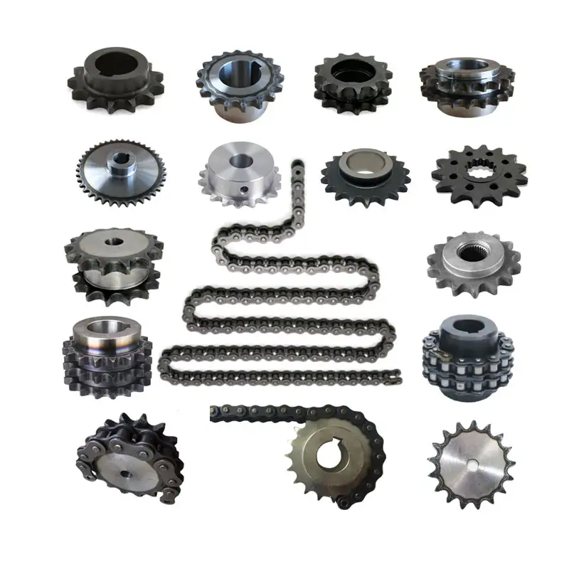
Noise and Vibration in wheel sprocket Configurations
In a wheel sprocket configuration, noise and vibration levels can vary depending on several factors:
- Quality of Components: The quality of the wheel sprocket components can significantly impact noise and vibration. Well-manufactured and precisely engineered components tend to produce less noise and vibration.
- Lubrication: Proper lubrication of the sprocket teeth and chain or belt can reduce friction, which in turn helps minimize noise and vibration.
- Alignment: Correct alignment between the wheel sprocket is crucial. Misalignment can lead to increased noise and vibration as the components may not mesh smoothly.
- Tension: Maintaining the appropriate tension in the chain or belt is essential. Insufficient tension can cause the chain to slap against the sprocket teeth, resulting in noise and vibration.
- Speed and Load: Higher speeds and heavier loads can lead to increased noise and vibration levels in the system.
- Wear and Damage: Worn-out or damaged components can create irregularities in motion, leading to increased noise and vibration.
To reduce noise and vibration in a wheel sprocket setup:
- Use high-quality components from reputable suppliers.
- Ensure proper lubrication with appropriate lubricants.
- Regularly inspect and maintain the system to detect any misalignment, wear, or damage.
- Follow manufacturer guidelines for chain or belt tensioning.
- Consider using vibration-damping materials or mounting methods if necessary.
Minimizing noise and vibration not only improves the comfort and safety of the machinery but also extends the life of the components by reducing wear and fatigue.
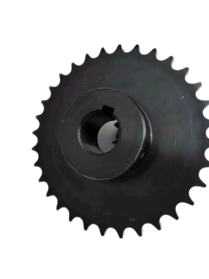
Advantages of Using a wheel sprocket Configuration
Using a wheel sprocket configuration for power transmission offers several advantages over other methods. Here are some key benefits:
1. Efficient Power Transmission:
The wheel sprocket assembly provide a highly efficient method of transmitting power between shafts with minimal energy loss. The teeth of the sprocket mesh with the links of the chain or the teeth of another sprocket, ensuring a positive engagement that reduces slippage and maximizes power transfer.
2. Versatility:
Wheels and sprockets are available in various sizes, configurations, and materials, making them highly versatile components for different applications. They can accommodate a wide range of speed and torque requirements, making them suitable for various mechanical systems.
3. Compact Design:
The compact design of wheel sprocket assemblies allows for space-saving installations in machinery. The concentric arrangement of the components minimizes the overall footprint, making it ideal for applications with limited space.
4. Precise Speed Control:
By selecting sprockets with different numbers of teeth, the gear ratio can be easily adjusted to achieve precise speed control in the driven shaft. This level of control is essential for many applications, such as conveyor systems, where different speeds are required for different processes.
5. High Torque Capacity:
wheel sprocket systems can handle high torque loads, making them suitable for heavy-duty applications. This high torque capacity is especially beneficial in industrial settings where large loads need to be moved or lifted.
6. Smooth and Quiet Operation:
When properly lubricated and maintained, the interaction between the sprocket and the chain or other sprockets results in smooth and quiet operation. This makes wheel sprocket systems preferable in applications where noise reduction is important.
7. Easy Installation and Maintenance:
Installing a wheel sprocket assembly is relatively straightforward, and they require minimal maintenance when used correctly. Periodic lubrication and tension adjustments are typically all that is needed to keep the system running smoothly.
8. Suitable for High-Speed Applications:
wheel sprocket configurations are well-suited for high-speed applications where belts or gears may not be as practical due to limitations in speed capabilities.
In summary, the wheel sprocket configuration offers efficient power transmission, versatility, compactness, precise speed control, high torque capacity, smooth operation, and ease of installation and maintenance. These advantages make it a popular choice in a wide range of mechanical systems and industrial applications.
editor by CX 2023-08-07
China high quality Gearbox Transmission Belt Parts Attachment Products 15 a Series Short Pitch Precision Simplex Roller Chains and Bush Chains for Agriculture
Product Description
A Series Short pitch Precision Simplex Roller Chains & Bush Chains
| ISO/ANSI/ DIN Chain No. |
China Chain No. |
Pitch P mm |
Roller diameter
d1max |
Width between inner plates b1min mm |
Pin diameter
d2max |
Pin length | Inner plate depth h2max mm |
Plate thickness
Tmax |
Tensile strength
Qmin |
Average tensile strength Q0 kN |
Weight per meter q kg/m |
|
| Lmax mm |
Lcmax mm |
|||||||||||
| 15 | *03C | 4.7625 | 2.48 | 2.38 | 1.62 | 6.10 | 6.90 | 4.30 | 0.60 | 1.80/409 | 2.0 | 0.08 |
*Bush chain:d1 in the table indicates the external diameter of the bush
ROLLER CHAIN
Roller chain or bush roller chain is the type of chain drive most commonly used for transmission of mechanical power on many kinds of domestic, industrial and agricultural machinery, including conveyors, wire- and tube-drawing machines, printing presses, cars, motorcycles, and bicycles. It consists of a series of short cylindrical rollers held together by side links. It is driven by a toothed wheel called a sprocket. It is a simple, reliable, and efficient means of power transmission.
CONSTRUCTION OF THE CHAIN
Two different sizes of roller chain, showing construction.
There are 2 types of links alternating in the bush roller chain. The first type is inner links, having 2 inner plates held together by 2 sleeves or bushings CZPT which rotate 2 rollers. Inner links alternate with the second type, the outer links, consisting of 2 outer plates held together by pins passing through the bushings of the inner links. The “bushingless” roller chain is similar in operation though not in construction; instead of separate bushings or sleeves holding the inner plates together, the plate has a tube stamped into it protruding from the hole which serves the same purpose. This has the advantage of removing 1 step in assembly of the chain.
The roller chain design reduces friction compared to simpler designs, resulting in higher efficiency and less wear. The original power transmission chain varieties lacked rollers and bushings, with both the inner and outer plates held by pins which directly contacted the sprocket teeth; however this configuration exhibited extremely rapid wear of both the sprocket teeth, and the plates where they pivoted on the pins. This problem was partially solved by the development of bushed chains, with the pins holding the outer plates passing through bushings or sleeves connecting the inner plates. This distributed the wear over a greater area; however the teeth of the sprockets still wore more rapidly than is desirable, from the sliding friction against the bushings. The addition of rollers surrounding the bushing sleeves of the chain and provided rolling contact with the teeth of the sprockets resulting in excellent resistance to wear of both sprockets and chain as well. There is even very low friction, as long as the chain is sufficiently lubricated. Continuous, clean, lubrication of roller chains is of primary importance for efficient operation as well as correct tensioning.
LUBRICATION
Many driving chains (for example, in factory equipment, or driving a camshaft inside an internal combustion engine) operate in clean environments, and thus the wearing surfaces (that is, the pins and bushings) are safe from precipitation and airborne grit, many even in a sealed environment such as an oil bath. Some roller chains are designed to have o-rings built into the space between the outside link plate and the inside roller link plates. Chain manufacturers began to include this feature in 1971 after the application was invented by Joseph Montano while working for Whitney Chain of Hartford, Connecticut. O-rings were included as a way to improve lubrication to the links of power transmission chains, a service that is vitally important to extending their working life. These rubber fixtures form a barrier that holds factory applied lubricating grease inside the pin and bushing wear areas. Further, the rubber o-rings prevent dirt and other contaminants from entering inside the chain linkages, where such particles would otherwise cause significant wear.[citation needed]
There are also many chains that have to operate in dirty conditions, and for size or operational reasons cannot be sealed. Examples include chains on farm equipment, bicycles, and chain saws. These chains will necessarily have relatively high rates of wear, particularly when the operators are prepared to accept more friction, less efficiency, more noise and more frequent replacement as they neglect lubrication and adjustment.
Many oil-based lubricants attract dirt and other particles, eventually forming an CZPT paste that will compound wear on chains. This problem can be circumvented by use of a “dry” PTFE spray, which forms a solid film after application and repels both particles and moisture.
VARIANTS DESIGN
Layout of a roller chain: 1. Outer plate, 2. Inner plate, 3. Pin, 4. Bushing, 5. Roller
If the chain is not being used for a high wear application (for instance if it is just transmitting motion from a hand-operated lever to a control shaft on a machine, or a sliding door on an oven), then 1 of the simpler types of chain may still be used. Conversely, where extra strength but the smooth drive of a smaller pitch is required, the chain may be “siamesed”; instead of just 2 rows of plates on the outer sides of the chain, there may be 3 (“duplex”), 4 (“triplex”), or more rows of plates running parallel, with bushings and rollers between each adjacent pair, and the same number of rows of teeth running in parallel on the sprockets to match. Timing chains on automotive engines, for example, typically have multiple rows of plates called strands.
Roller chain is made in several sizes, the most common American National Standards Institute (ANSI) standards being 40, 50, 60, and 80. The first digit(s) indicate the pitch of the chain in eighths of an inch, with the last digit being 0 for standard chain, 1 for lightweight chain, and 5 for bushed chain with no rollers. Thus, a chain with half-inch pitch would be a #40 while a #160 sprocket would have teeth spaced 2 inches apart, etc. Metric pitches are expressed in sixteenths of an inch; thus a metric #8 chain (08B-1) would be equivalent to an ANSI #40. Most roller chain is made from plain carbon or alloy steel, but stainless steel is used in food processing machinery or other places where lubrication is a problem, and nylon or brass are occasionally seen for the same reason.
Roller chain is ordinarily hooked up using a master link (also known as a connecting link), which typically has 1 pin held by a horseshoe clip rather than friction fit, allowing it to be inserted or removed with simple tools. Chain with a removable link or pin is also known as cottered chain, which allows the length of the chain to be adjusted. Half links (also known as offsets) are available and are used to increase the length of the chain by a single roller. Riveted roller chain has the master link (also known as a connecting link) “riveted” or mashed on the ends. These pins are made to be durable and are not removable.
USE
An example of 2 ‘ghost’ sprockets tensioning a triplex roller chain system
Roller chains are used in low- to mid-speed drives at around 600 to 800 feet per minute; however, at higher speeds, around 2,000 to 3,000 feet per minute, V-belts are normally used due to wear and noise issues.
A bicycle chain is a form of roller chain. Bicycle chains may have a master link, or may require a chain tool for removal and installation. A similar but larger and thus stronger chain is used on most motorcycles although it is sometimes replaced by either a toothed belt or a shaft drive, which offer lower noise level and fewer maintenance requirements.
The great majority of automobile engines use roller chains to drive the camshaft(s). Very high performance engines often use gear drive, and starting in the early 1960s toothed belts were used by some manufacturers.
Chains are also used in forklifts using hydraulic rams as a pulley to raise and lower the carriage; however, these chains are not considered roller chains, but are classified as lift or leaf chains.
Chainsaw cutting chains superficially resemble roller chains but are more closely related to leaf chains. They are driven by projecting drive links which also serve to locate the chain CZPT the bar.
Sea Harrier FA.2 ZA195 front (cold) vector thrust nozzle – the nozzle is rotated by a chain drive from an air motor
A perhaps unusual use of a pair of motorcycle chains is in the Harrier Jump Jet, where a chain drive from an air motor is used to rotate the movable engine nozzles, allowing them to be pointed downwards for hovering flight, or to the rear for normal CZPT flight, a system known as Thrust vectoring.
WEAR
The effect of wear on a roller chain is to increase the pitch (spacing of the links), causing the chain to grow longer. Note that this is due to wear at the pivoting pins and bushes, not from actual stretching of the metal (as does happen to some flexible steel components such as the hand-brake cable of a motor vehicle).
With modern chains it is unusual for a chain (other than that of a bicycle) to wear until it breaks, since a worn chain leads to the rapid onset of wear on the teeth of the sprockets, with ultimate failure being the loss of all the teeth on the sprocket. The sprockets (in particular the smaller of the two) suffer a grinding motion that puts a characteristic hook shape into the driven face of the teeth. (This effect is made worse by a chain improperly tensioned, but is unavoidable no matter what care is taken). The worn teeth (and chain) no longer provides smooth transmission of power and this may become evident from the noise, the vibration or (in car engines using a timing chain) the variation in ignition timing seen with a timing light. Both sprockets and chain should be replaced in these cases, since a new chain on worn sprockets will not last long. However, in less severe cases it may be possible to save the larger of the 2 sprockets, since it is always the smaller 1 that suffers the most wear. Only in very light-weight applications such as a bicycle, or in extreme cases of improper tension, will the chain normally jump off the sprockets.
The lengthening due to wear of a chain is calculated by the following formula:
M = the length of a number of links measured
S = the number of links measured
P = Pitch
In industry, it is usual to monitor the movement of the chain tensioner (whether manual or automatic) or the exact length of a drive chain (one rule of thumb is to replace a roller chain which has elongated 3% on an adjustable drive or 1.5% on a fixed-center drive). A simpler method, particularly suitable for the cycle or motorcycle user, is to attempt to pull the chain away from the larger of the 2 sprockets, whilst ensuring the chain is taut. Any significant movement (e.g. making it possible to see through a gap) probably indicates a chain worn up to and beyond the limit. Sprocket damage will result if the problem is ignored. Sprocket wear cancels this effect, and may mask chain wear.
CHAIN STRENGTH
The most common measure of roller chain’s strength is tensile strength. Tensile strength represents how much load a chain can withstand under a one-time load before breaking. Just as important as tensile strength is a chain’s fatigue strength. The critical factors in a chain’s fatigue strength is the quality of steel used to manufacture the chain, the heat treatment of the chain components, the quality of the pitch hole fabrication of the linkplates, and the type of shot plus the intensity of shot peen coverage on the linkplates. Other factors can include the thickness of the linkplates and the design (contour) of the linkplates. The rule of thumb for roller chain operating on a continuous drive is for the chain load to not exceed a mere 1/6 or 1/9 of the chain’s tensile strength, depending on the type of master links used (press-fit vs. slip-fit)[citation needed]. Roller chains operating on a continuous drive beyond these thresholds can and typically do fail prematurely via linkplate fatigue failure.
The standard minimum ultimate strength of the ANSI 29.1 steel chain is 12,500 x (pitch, in inches)2. X-ring and O-Ring chains greatly decrease wear by means of internal lubricants, increasing chain life. The internal lubrication is inserted by means of a vacuum when riveting the chain together.
CHAIN STHangZhouRDS
Standards organizations (such as ANSI and ISO) maintain standards for design, dimensions, and interchangeability of transmission chains. For example, the following Table shows data from ANSI standard B29.1-2011 (Precision Power Transmission Roller Chains, Attachments, and Sprockets) developed by the American Society of Mechanical Engineers (ASME). See the references[8][9][10] for additional information.
ASME/ANSI B29.1-2011 Roller Chain Standard SizesSizePitchMaximum Roller DiameterMinimum Ultimate Tensile StrengthMeasuring Load25
| ASME/ANSI B29.1-2011 Roller Chain Standard Sizes | ||||
| Size | Pitch | Maximum Roller Diameter | Minimum Ultimate Tensile Strength | Measuring Load |
|---|---|---|---|---|
| 25 | 0.250 in (6.35 mm) | 0.130 in (3.30 mm) | 780 lb (350 kg) | 18 lb (8.2 kg) |
| 35 | 0.375 in (9.53 mm) | 0.200 in (5.08 mm) | 1,760 lb (800 kg) | 18 lb (8.2 kg) |
| 41 | 0.500 in (12.70 mm) | 0.306 in (7.77 mm) | 1,500 lb (680 kg) | 18 lb (8.2 kg) |
| 40 | 0.500 in (12.70 mm) | 0.312 in (7.92 mm) | 3,125 lb (1,417 kg) | 31 lb (14 kg) |
| 50 | 0.625 in (15.88 mm) | 0.400 in (10.16 mm) | 4,880 lb (2,210 kg) | 49 lb (22 kg) |
| 60 | 0.750 in (19.05 mm) | 0.469 in (11.91 mm) | 7,030 lb (3,190 kg) | 70 lb (32 kg) |
| 80 | 1.000 in (25.40 mm) | 0.625 in (15.88 mm) | 12,500 lb (5,700 kg) | 125 lb (57 kg) |
| 100 | 1.250 in (31.75 mm) | 0.750 in (19.05 mm) | 19,531 lb (8,859 kg) | 195 lb (88 kg) |
| 120 | 1.500 in (38.10 mm) | 0.875 in (22.23 mm) | 28,125 lb (12,757 kg) | 281 lb (127 kg) |
| 140 | 1.750 in (44.45 mm) | 1.000 in (25.40 mm) | 38,280 lb (17,360 kg) | 383 lb (174 kg) |
| 160 | 2.000 in (50.80 mm) | 1.125 in (28.58 mm) | 50,000 lb (23,000 kg) | 500 lb (230 kg) |
| 180 | 2.250 in (57.15 mm) | 1.460 in (37.08 mm) | 63,280 lb (28,700 kg) | 633 lb (287 kg) |
| 200 | 2.500 in (63.50 mm) | 1.562 in (39.67 mm) | 78,175 lb (35,460 kg) | 781 lb (354 kg) |
| 240 | 3.000 in (76.20 mm) | 1.875 in (47.63 mm) | 112,500 lb (51,000 kg) | 1,000 lb (450 kg |
For mnemonic purposes, below is another presentation of key dimensions from the same standard, expressed in fractions of an inch (which was part of the thinking behind the choice of preferred numbers in the ANSI standard):
| Pitch (inches) | Pitch expressed in eighths |
ANSI standard chain number |
Width (inches) |
|---|---|---|---|
| 1⁄4 | 2⁄8 | 25 | 1⁄8 |
| 3⁄8 | 3⁄8 | 35 | 3⁄16 |
| 1⁄2 | 4⁄8 | 41 | 1⁄4 |
| 1⁄2 | 4⁄8 | 40 | 5⁄16 |
| 5⁄8 | 5⁄8 | 50 | 3⁄8 |
| 3⁄4 | 6⁄8 | 60 | 1⁄2 |
| 1 | 8⁄8 | 80 | 5⁄8 |
Notes:
1. The pitch is the distance between roller centers. The width is the distance between the link plates (i.e. slightly more than the roller width to allow for clearance).
2. The right-hand digit of the standard denotes 0 = normal chain, 1 = lightweight chain, 5 = rollerless bushing chain.
3. The left-hand digit denotes the number of eighths of an inch that make up the pitch.
4. An “H” following the standard number denotes heavyweight chain. A hyphenated number following the standard number denotes double-strand (2), triple-strand (3), and so on. Thus 60H-3 denotes number 60 heavyweight triple-strand chain.
A typical bicycle chain (for derailleur gears) uses narrow 1⁄2-inch-pitch chain. The width of the chain is variable, and does not affect the load capacity. The more sprockets at the rear wheel (historically 3-6, nowadays 7-12 sprockets), the narrower the chain. Chains are sold according to the number of speeds they are designed to work with, for example, “10 speed chain”. Hub gear or single speed bicycles use 1/2″ x 1/8″ chains, where 1/8″ refers to the maximum thickness of a sprocket that can be used with the chain.
Typically chains with parallel shaped links have an even number of links, with each narrow link followed by a broad one. Chains built up with a uniform type of link, narrow at 1 and broad at the other end, can be made with an odd number of links, which can be an advantage to adapt to a special chainwheel-distance; on the other side such a chain tends to be not so strong.
Roller chains made using ISO standard are sometimes called as isochains.
WHY CHOOSE US
1. Reliable Quality Assurance System
2. Cutting-Edge Computer-Controlled CNC Machines
3. Bespoke Solutions from Highly Experienced Specialists
4. Customization and OEM Available for Specific Application
5. Extensive Inventory of Spare Parts and Accessories
6. Well-Developed CZPT Marketing Network
7. Efficient After-Sale Service System
The 219 sets of advanced automatic production equipment provide guarantees for high product quality. The 167 engineers and technicians with senior professional titles can design and develop products to meet the exact demands of customers, and OEM customizations are also available with us. Our sound global service network can provide customers with timely after-sales technical services.
We are not just a manufacturer and supplier, but also an industry consultant. We work pro-actively with you to offer expert advice and product recommendations in order to end up with a most cost effective product available for your specific application. The clients we serve CZPT range from end users to distributors and OEMs. Our OEM replacements can be substituted wherever necessary and suitable for both repair and new assemblies.
|
Shipping Cost:
Estimated freight per unit. |
To be negotiated |
|---|
| Standard or Nonstandard: | Standard |
|---|---|
| Application: | Textile Machinery, Garment Machinery, Conveyer Equipment, Packaging Machinery, Electric Cars, Motorcycle, Food Machinery, Marine, Mining Equipment, Agricultural Machinery, Car |
| Surface Treatment: | Polishing |
| Samples: |
US$ 3/Meter
1 Meter(Min.Order) | Order Sample |
|---|
| Customization: |
Available
| Customized Request |
|---|

How does the choice of chain attachment affect the functionality of a transmission chain?
The choice of chain attachment plays a critical role in the functionality and performance of a transmission chain. Here’s a detailed answer to the question:
1. Load Capacity: Different chain attachments are designed to handle specific types and amounts of loads. The selection of the appropriate attachment is crucial to ensure that the transmission chain can safely and efficiently carry the intended load. The type of attachment, such as extended pins, cleats, or slats, can determine the chain’s ability to handle heavy or irregular loads.
2. Application Compatibility: The choice of chain attachment should align with the specific application requirements. Different industries and applications may require specialized attachments that are designed to address particular challenges or provide specific functionalities. For example, attachments used in conveying systems may include rollers, flights, or grippers to facilitate smooth material transfer.
3. Alignment and Tracking: Certain chain attachments, such as guide rails or track systems, help to ensure proper alignment and tracking of the transmission chain. These attachments minimize the risk of chain derailment or misalignment, which can lead to operational issues and reduced efficiency.
4. Positioning and Orientation: Some applications require precise positioning or orientation of objects or components. Chain attachments, such as indexing pins or brackets, are designed to facilitate accurate positioning or rotation of objects along the chain’s path. These attachments contribute to the reliable and precise operation of the transmission chain.
5. Material Handling: In material handling applications, chain attachments are often used to secure or hold items during transport. Attachments like hooks, clamps, or brackets enable the secure attachment of objects to the chain, preventing slippage or displacement during movement. This ensures safe and efficient material handling operations.
6. Specialized Functions: Chain attachments can provide additional functions based on specific application requirements. For example, attachments such as sensors, RFID tags, or lubrication reservoirs can be integrated into the chain design to enable monitoring, tracking, or lubrication functions. These specialized attachments enhance the overall functionality and performance of the transmission chain.
It’s important to select the appropriate chain attachment based on the specific application needs, load requirements, and desired functionality. Consulting with industry experts or chain manufacturers can help in determining the most suitable attachment options for optimal transmission chain performance.
What are the benefits of using a lightweight transmission chain?
Using a lightweight transmission chain offers several advantages. Here’s a detailed answer to the question:
1. Improved Efficiency: A lightweight transmission chain reduces the overall weight of the system, resulting in improved energy efficiency. With less mass to move, the power required to drive the chain is reduced, leading to lower energy consumption.
2. Increased Power-to-Weight Ratio: The lightweight nature of the chain allows for a higher power-to-weight ratio. This means that a smaller, lighter chain can transmit the same amount of power as a heavier chain, making it suitable for applications where weight reduction is crucial, such as in portable or handheld equipment.
3. Reduced Inertia: The lower weight of the transmission chain reduces the inertia of the system. This enables faster acceleration and deceleration, resulting in improved response times and better overall performance in dynamic applications.
4. Easier Handling and Installation: Lightweight transmission chains are easier to handle and install compared to heavier chains. They require less effort and manpower during installation or maintenance activities, making them more convenient and time-saving.
5. Lower Wear and Tear: The reduced weight of the chain contributes to lower wear and tear on other components of the system, such as sprockets, bearings, and shafts. This can extend the lifespan of these components and reduce the frequency of maintenance and replacement.
6. Cost Savings: Using a lightweight transmission chain can result in cost savings in several ways. The reduced energy consumption leads to lower operating costs, and the lighter weight may allow for the use of smaller and less expensive supporting components.
It’s important to note that the choice of a lightweight transmission chain should be based on the specific application requirements. Factors such as load capacity, speed, operating environment, and compatibility with other system components should be considered to ensure that the lightweight chain meets the performance and durability needs of the application.

What are the key components of a transmission chain?
A transmission chain consists of several key components that work together to transmit power and motion efficiently. The main components of a transmission chain include:
- Inner Plates: These are flat metal plates with holes or slots for connecting the other components of the chain.
- Outer Plates: Similar to inner plates, outer plates provide additional strength and support to the chain.
- Pins: The pins hold the inner and outer plates together, creating a flexible link between them. They play a crucial role in maintaining the integrity and functionality of the chain.
- Bushings: Bushings are cylindrical components that fit into the holes of the inner and outer plates. They provide a smooth surface for the chain to rotate around the pins.
- Rollers: Rollers are cylindrical elements that fit between the inner plates and the bushings. They reduce friction and enable smooth movement as the chain engages with the sprockets.
- Solid Bushings (optional): In some transmission chains, solid bushings may be used instead of bushings with holes. Solid bushings provide additional strength and stability to the chain.
- Sprockets: Sprockets are toothed wheels that engage with the rollers of the transmission chain. They transfer power and motion to the chain, enabling it to drive various machinery and equipment.
These components work together to form a continuous loop that transmits power from the driving sprocket to the driven sprocket, allowing the chain to transfer rotational motion and drive various mechanical systems.
editor by CX 2023-08-04
China supplier Gearbox Transmission Belt Parts Attachment Products 15 a Series Short Pitch Precision Simplex Roller Chains and Bush Chains for Agriculture
Product Description
A Series Short pitch Precision Simplex Roller Chains & Bush Chains
| ISO/ANSI/ DIN Chain No. |
China Chain No. |
Pitch P mm |
Roller diameter
d1max |
Width between inner plates b1min mm |
Pin diameter
d2max |
Pin length | Inner plate depth h2max mm |
Plate thickness
Tmax |
Tensile strength
Qmin |
Average tensile strength Q0 kN |
Weight per meter q kg/m |
|
| Lmax mm |
Lcmax mm |
|||||||||||
| 15 | *03C | 4.7625 | 2.48 | 2.38 | 1.62 | 6.10 | 6.90 | 4.30 | 0.60 | 1.80/409 | 2.0 | 0.08 |
*Bush chain:d1 in the table indicates the external diameter of the bush
ROLLER CHAIN
Roller chain or bush roller chain is the type of chain drive most commonly used for transmission of mechanical power on many kinds of domestic, industrial and agricultural machinery, including conveyors, wire- and tube-drawing machines, printing presses, cars, motorcycles, and bicycles. It consists of a series of short cylindrical rollers held together by side links. It is driven by a toothed wheel called a sprocket. It is a simple, reliable, and efficient means of power transmission.
CONSTRUCTION OF THE CHAIN
Two different sizes of roller chain, showing construction.
There are 2 types of links alternating in the bush roller chain. The first type is inner links, having 2 inner plates held together by 2 sleeves or bushings CZPT which rotate 2 rollers. Inner links alternate with the second type, the outer links, consisting of 2 outer plates held together by pins passing through the bushings of the inner links. The “bushingless” roller chain is similar in operation though not in construction; instead of separate bushings or sleeves holding the inner plates together, the plate has a tube stamped into it protruding from the hole which serves the same purpose. This has the advantage of removing 1 step in assembly of the chain.
The roller chain design reduces friction compared to simpler designs, resulting in higher efficiency and less wear. The original power transmission chain varieties lacked rollers and bushings, with both the inner and outer plates held by pins which directly contacted the sprocket teeth; however this configuration exhibited extremely rapid wear of both the sprocket teeth, and the plates where they pivoted on the pins. This problem was partially solved by the development of bushed chains, with the pins holding the outer plates passing through bushings or sleeves connecting the inner plates. This distributed the wear over a greater area; however the teeth of the sprockets still wore more rapidly than is desirable, from the sliding friction against the bushings. The addition of rollers surrounding the bushing sleeves of the chain and provided rolling contact with the teeth of the sprockets resulting in excellent resistance to wear of both sprockets and chain as well. There is even very low friction, as long as the chain is sufficiently lubricated. Continuous, clean, lubrication of roller chains is of primary importance for efficient operation as well as correct tensioning.
LUBRICATION
Many driving chains (for example, in factory equipment, or driving a camshaft inside an internal combustion engine) operate in clean environments, and thus the wearing surfaces (that is, the pins and bushings) are safe from precipitation and airborne grit, many even in a sealed environment such as an oil bath. Some roller chains are designed to have o-rings built into the space between the outside link plate and the inside roller link plates. Chain manufacturers began to include this feature in 1971 after the application was invented by Joseph Montano while working for Whitney Chain of Hartford, Connecticut. O-rings were included as a way to improve lubrication to the links of power transmission chains, a service that is vitally important to extending their working life. These rubber fixtures form a barrier that holds factory applied lubricating grease inside the pin and bushing wear areas. Further, the rubber o-rings prevent dirt and other contaminants from entering inside the chain linkages, where such particles would otherwise cause significant wear.[citation needed]
There are also many chains that have to operate in dirty conditions, and for size or operational reasons cannot be sealed. Examples include chains on farm equipment, bicycles, and chain saws. These chains will necessarily have relatively high rates of wear, particularly when the operators are prepared to accept more friction, less efficiency, more noise and more frequent replacement as they neglect lubrication and adjustment.
Many oil-based lubricants attract dirt and other particles, eventually forming an CZPT paste that will compound wear on chains. This problem can be circumvented by use of a “dry” PTFE spray, which forms a solid film after application and repels both particles and moisture.
VARIANTS DESIGN
Layout of a roller chain: 1. Outer plate, 2. Inner plate, 3. Pin, 4. Bushing, 5. Roller
If the chain is not being used for a high wear application (for instance if it is just transmitting motion from a hand-operated lever to a control shaft on a machine, or a sliding door on an oven), then 1 of the simpler types of chain may still be used. Conversely, where extra strength but the smooth drive of a smaller pitch is required, the chain may be “siamesed”; instead of just 2 rows of plates on the outer sides of the chain, there may be 3 (“duplex”), 4 (“triplex”), or more rows of plates running parallel, with bushings and rollers between each adjacent pair, and the same number of rows of teeth running in parallel on the sprockets to match. Timing chains on automotive engines, for example, typically have multiple rows of plates called strands.
Roller chain is made in several sizes, the most common American National Standards Institute (ANSI) standards being 40, 50, 60, and 80. The first digit(s) indicate the pitch of the chain in eighths of an inch, with the last digit being 0 for standard chain, 1 for lightweight chain, and 5 for bushed chain with no rollers. Thus, a chain with half-inch pitch would be a #40 while a #160 sprocket would have teeth spaced 2 inches apart, etc. Metric pitches are expressed in sixteenths of an inch; thus a metric #8 chain (08B-1) would be equivalent to an ANSI #40. Most roller chain is made from plain carbon or alloy steel, but stainless steel is used in food processing machinery or other places where lubrication is a problem, and nylon or brass are occasionally seen for the same reason.
Roller chain is ordinarily hooked up using a master link (also known as a connecting link), which typically has 1 pin held by a horseshoe clip rather than friction fit, allowing it to be inserted or removed with simple tools. Chain with a removable link or pin is also known as cottered chain, which allows the length of the chain to be adjusted. Half links (also known as offsets) are available and are used to increase the length of the chain by a single roller. Riveted roller chain has the master link (also known as a connecting link) “riveted” or mashed on the ends. These pins are made to be durable and are not removable.
USE
An example of 2 ‘ghost’ sprockets tensioning a triplex roller chain system
Roller chains are used in low- to mid-speed drives at around 600 to 800 feet per minute; however, at higher speeds, around 2,000 to 3,000 feet per minute, V-belts are normally used due to wear and noise issues.
A bicycle chain is a form of roller chain. Bicycle chains may have a master link, or may require a chain tool for removal and installation. A similar but larger and thus stronger chain is used on most motorcycles although it is sometimes replaced by either a toothed belt or a shaft drive, which offer lower noise level and fewer maintenance requirements.
The great majority of automobile engines use roller chains to drive the camshaft(s). Very high performance engines often use gear drive, and starting in the early 1960s toothed belts were used by some manufacturers.
Chains are also used in forklifts using hydraulic rams as a pulley to raise and lower the carriage; however, these chains are not considered roller chains, but are classified as lift or leaf chains.
Chainsaw cutting chains superficially resemble roller chains but are more closely related to leaf chains. They are driven by projecting drive links which also serve to locate the chain CZPT the bar.
Sea Harrier FA.2 ZA195 front (cold) vector thrust nozzle – the nozzle is rotated by a chain drive from an air motor
A perhaps unusual use of a pair of motorcycle chains is in the Harrier Jump Jet, where a chain drive from an air motor is used to rotate the movable engine nozzles, allowing them to be pointed downwards for hovering flight, or to the rear for normal CZPT flight, a system known as Thrust vectoring.
WEAR
The effect of wear on a roller chain is to increase the pitch (spacing of the links), causing the chain to grow longer. Note that this is due to wear at the pivoting pins and bushes, not from actual stretching of the metal (as does happen to some flexible steel components such as the hand-brake cable of a motor vehicle).
With modern chains it is unusual for a chain (other than that of a bicycle) to wear until it breaks, since a worn chain leads to the rapid onset of wear on the teeth of the sprockets, with ultimate failure being the loss of all the teeth on the sprocket. The sprockets (in particular the smaller of the two) suffer a grinding motion that puts a characteristic hook shape into the driven face of the teeth. (This effect is made worse by a chain improperly tensioned, but is unavoidable no matter what care is taken). The worn teeth (and chain) no longer provides smooth transmission of power and this may become evident from the noise, the vibration or (in car engines using a timing chain) the variation in ignition timing seen with a timing light. Both sprockets and chain should be replaced in these cases, since a new chain on worn sprockets will not last long. However, in less severe cases it may be possible to save the larger of the 2 sprockets, since it is always the smaller 1 that suffers the most wear. Only in very light-weight applications such as a bicycle, or in extreme cases of improper tension, will the chain normally jump off the sprockets.
The lengthening due to wear of a chain is calculated by the following formula:
M = the length of a number of links measured
S = the number of links measured
P = Pitch
In industry, it is usual to monitor the movement of the chain tensioner (whether manual or automatic) or the exact length of a drive chain (one rule of thumb is to replace a roller chain which has elongated 3% on an adjustable drive or 1.5% on a fixed-center drive). A simpler method, particularly suitable for the cycle or motorcycle user, is to attempt to pull the chain away from the larger of the 2 sprockets, whilst ensuring the chain is taut. Any significant movement (e.g. making it possible to see through a gap) probably indicates a chain worn up to and beyond the limit. Sprocket damage will result if the problem is ignored. Sprocket wear cancels this effect, and may mask chain wear.
CHAIN STRENGTH
The most common measure of roller chain’s strength is tensile strength. Tensile strength represents how much load a chain can withstand under a one-time load before breaking. Just as important as tensile strength is a chain’s fatigue strength. The critical factors in a chain’s fatigue strength is the quality of steel used to manufacture the chain, the heat treatment of the chain components, the quality of the pitch hole fabrication of the linkplates, and the type of shot plus the intensity of shot peen coverage on the linkplates. Other factors can include the thickness of the linkplates and the design (contour) of the linkplates. The rule of thumb for roller chain operating on a continuous drive is for the chain load to not exceed a mere 1/6 or 1/9 of the chain’s tensile strength, depending on the type of master links used (press-fit vs. slip-fit)[citation needed]. Roller chains operating on a continuous drive beyond these thresholds can and typically do fail prematurely via linkplate fatigue failure.
The standard minimum ultimate strength of the ANSI 29.1 steel chain is 12,500 x (pitch, in inches)2. X-ring and O-Ring chains greatly decrease wear by means of internal lubricants, increasing chain life. The internal lubrication is inserted by means of a vacuum when riveting the chain together.
CHAIN STHangZhouRDS
Standards organizations (such as ANSI and ISO) maintain standards for design, dimensions, and interchangeability of transmission chains. For example, the following Table shows data from ANSI standard B29.1-2011 (Precision Power Transmission Roller Chains, Attachments, and Sprockets) developed by the American Society of Mechanical Engineers (ASME). See the references[8][9][10] for additional information.
ASME/ANSI B29.1-2011 Roller Chain Standard SizesSizePitchMaximum Roller DiameterMinimum Ultimate Tensile StrengthMeasuring Load25
| ASME/ANSI B29.1-2011 Roller Chain Standard Sizes | ||||
| Size | Pitch | Maximum Roller Diameter | Minimum Ultimate Tensile Strength | Measuring Load |
|---|---|---|---|---|
| 25 | 0.250 in (6.35 mm) | 0.130 in (3.30 mm) | 780 lb (350 kg) | 18 lb (8.2 kg) |
| 35 | 0.375 in (9.53 mm) | 0.200 in (5.08 mm) | 1,760 lb (800 kg) | 18 lb (8.2 kg) |
| 41 | 0.500 in (12.70 mm) | 0.306 in (7.77 mm) | 1,500 lb (680 kg) | 18 lb (8.2 kg) |
| 40 | 0.500 in (12.70 mm) | 0.312 in (7.92 mm) | 3,125 lb (1,417 kg) | 31 lb (14 kg) |
| 50 | 0.625 in (15.88 mm) | 0.400 in (10.16 mm) | 4,880 lb (2,210 kg) | 49 lb (22 kg) |
| 60 | 0.750 in (19.05 mm) | 0.469 in (11.91 mm) | 7,030 lb (3,190 kg) | 70 lb (32 kg) |
| 80 | 1.000 in (25.40 mm) | 0.625 in (15.88 mm) | 12,500 lb (5,700 kg) | 125 lb (57 kg) |
| 100 | 1.250 in (31.75 mm) | 0.750 in (19.05 mm) | 19,531 lb (8,859 kg) | 195 lb (88 kg) |
| 120 | 1.500 in (38.10 mm) | 0.875 in (22.23 mm) | 28,125 lb (12,757 kg) | 281 lb (127 kg) |
| 140 | 1.750 in (44.45 mm) | 1.000 in (25.40 mm) | 38,280 lb (17,360 kg) | 383 lb (174 kg) |
| 160 | 2.000 in (50.80 mm) | 1.125 in (28.58 mm) | 50,000 lb (23,000 kg) | 500 lb (230 kg) |
| 180 | 2.250 in (57.15 mm) | 1.460 in (37.08 mm) | 63,280 lb (28,700 kg) | 633 lb (287 kg) |
| 200 | 2.500 in (63.50 mm) | 1.562 in (39.67 mm) | 78,175 lb (35,460 kg) | 781 lb (354 kg) |
| 240 | 3.000 in (76.20 mm) | 1.875 in (47.63 mm) | 112,500 lb (51,000 kg) | 1,000 lb (450 kg |
For mnemonic purposes, below is another presentation of key dimensions from the same standard, expressed in fractions of an inch (which was part of the thinking behind the choice of preferred numbers in the ANSI standard):
| Pitch (inches) | Pitch expressed in eighths |
ANSI standard chain number |
Width (inches) |
|---|---|---|---|
| 1⁄4 | 2⁄8 | 25 | 1⁄8 |
| 3⁄8 | 3⁄8 | 35 | 3⁄16 |
| 1⁄2 | 4⁄8 | 41 | 1⁄4 |
| 1⁄2 | 4⁄8 | 40 | 5⁄16 |
| 5⁄8 | 5⁄8 | 50 | 3⁄8 |
| 3⁄4 | 6⁄8 | 60 | 1⁄2 |
| 1 | 8⁄8 | 80 | 5⁄8 |
Notes:
1. The pitch is the distance between roller centers. The width is the distance between the link plates (i.e. slightly more than the roller width to allow for clearance).
2. The right-hand digit of the standard denotes 0 = normal chain, 1 = lightweight chain, 5 = rollerless bushing chain.
3. The left-hand digit denotes the number of eighths of an inch that make up the pitch.
4. An “H” following the standard number denotes heavyweight chain. A hyphenated number following the standard number denotes double-strand (2), triple-strand (3), and so on. Thus 60H-3 denotes number 60 heavyweight triple-strand chain.
A typical bicycle chain (for derailleur gears) uses narrow 1⁄2-inch-pitch chain. The width of the chain is variable, and does not affect the load capacity. The more sprockets at the rear wheel (historically 3-6, nowadays 7-12 sprockets), the narrower the chain. Chains are sold according to the number of speeds they are designed to work with, for example, “10 speed chain”. Hub gear or single speed bicycles use 1/2″ x 1/8″ chains, where 1/8″ refers to the maximum thickness of a sprocket that can be used with the chain.
Typically chains with parallel shaped links have an even number of links, with each narrow link followed by a broad one. Chains built up with a uniform type of link, narrow at 1 and broad at the other end, can be made with an odd number of links, which can be an advantage to adapt to a special chainwheel-distance; on the other side such a chain tends to be not so strong.
Roller chains made using ISO standard are sometimes called as isochains.
WHY CHOOSE US
1. Reliable Quality Assurance System
2. Cutting-Edge Computer-Controlled CNC Machines
3. Bespoke Solutions from Highly Experienced Specialists
4. Customization and OEM Available for Specific Application
5. Extensive Inventory of Spare Parts and Accessories
6. Well-Developed CZPT Marketing Network
7. Efficient After-Sale Service System
The 219 sets of advanced automatic production equipment provide guarantees for high product quality. The 167 engineers and technicians with senior professional titles can design and develop products to meet the exact demands of customers, and OEM customizations are also available with us. Our sound global service network can provide customers with timely after-sales technical services.
We are not just a manufacturer and supplier, but also an industry consultant. We work pro-actively with you to offer expert advice and product recommendations in order to end up with a most cost effective product available for your specific application. The clients we serve CZPT range from end users to distributors and OEMs. Our OEM replacements can be substituted wherever necessary and suitable for both repair and new assemblies.
|
Shipping Cost:
Estimated freight per unit. |
To be negotiated |
|---|
| Standard or Nonstandard: | Standard |
|---|---|
| Application: | Textile Machinery, Garment Machinery, Conveyer Equipment, Packaging Machinery, Electric Cars, Motorcycle, Food Machinery, Marine, Mining Equipment, Agricultural Machinery, Car |
| Surface Treatment: | Polishing |
| Samples: |
US$ 3/Meter
1 Meter(Min.Order) | Order Sample |
|---|
| Customization: |
Available
| Customized Request |
|---|
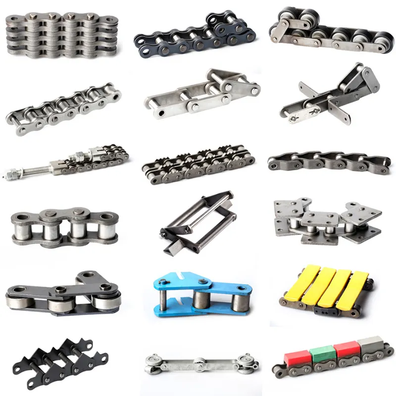
How does the length of a transmission chain impact its performance?
The length of a transmission chain plays a significant role in its overall performance and functionality. Here’s a detailed explanation:
1. Proper Fit and Function: The length of a transmission chain needs to be carefully selected to ensure it fits and functions correctly within the designated system. If the chain is too short, it may not be able to reach the sprockets or pulleys properly, leading to ineffective power transmission and potential chain slippage. On the other hand, if the chain is too long, it may sag, create excessive tension, or cause interference with other components, resulting in inefficient operation or premature wear.
2. Tension and Slack Control: The length of a transmission chain affects the tension and slack control within the system. A properly tensioned chain ensures optimal power transmission, reduces backlash, and minimizes the risk of chain derailment. The chain length must be adjusted to maintain the appropriate tension throughout the operating cycle, considering factors such as load variations, temperature changes, and system dynamics.
3. Flexibility and Bending Requirements: The length of a transmission chain influences its flexibility and bending characteristics. Longer chains may have a higher degree of flexibility, allowing them to navigate complex paths or accommodate greater distances between sprockets or pulleys. However, excessive chain length can lead to excessive bending, resulting in increased friction, wear, and potential premature failure.
4. Sprocket Interactions: The length of the transmission chain affects its interaction with the sprockets or pulleys. The number of chain links determines the engagement between the chain and the teeth of the sprockets. Proper length ensures smooth engagement, minimal tooth wear, and efficient power transfer. Incorrect chain length can cause misalignment, increased noise, and accelerated sprocket or chain wear.
5. System Efficiency and Performance: The length of a transmission chain directly impacts the overall efficiency and performance of the system. A properly sized chain ensures optimum power transmission, minimal energy losses, and reliable operation. By selecting the appropriate chain length, system designers can maximize efficiency, minimize wear, and optimize the lifespan of both the chain and related components.
When selecting the length of a transmission chain, it’s crucial to consider the specific requirements of the application, including the distance between sprockets or pulleys, the desired tension, and the expected load conditions. Consulting with chain manufacturers or industry experts can provide valuable guidance in determining the appropriate chain length for optimal performance and longevity.
How does the choice of material impact the performance of a transmission chain?
The choice of material for a transmission chain plays a crucial role in its overall performance and durability. Here’s a detailed answer to the question:
1. Strength and Load Capacity: Different materials have varying levels of strength and load-carrying capacities. High-strength materials like alloy steel or stainless steel offer superior strength and can withstand heavy loads. The choice of a material with adequate strength ensures that the transmission chain can handle the required load without premature wear or failure.
2. Wear Resistance: The material used in the construction of a transmission chain affects its wear resistance. Some materials, such as hardened steel or certain alloys, have excellent wear resistance properties, allowing the chain to withstand abrasive conditions and prolong its lifespan. Choosing a material with good wear resistance reduces the need for frequent chain replacements and maintenance.
3. Corrosion Resistance: In environments where corrosion is a concern, such as outdoor or corrosive industrial settings, selecting a material with high corrosion resistance is essential. Stainless steel or specially coated chains offer excellent resistance to rust and corrosion, ensuring reliable performance and longevity even in harsh conditions.
4. Fatigue Strength: The material’s fatigue strength is crucial in applications where the transmission chain undergoes repeated cyclic loading. Fatigue failure can occur when a chain is subjected to continuous stress cycles, leading to cracks and eventual failure. Materials with high fatigue strength, such as specific alloys or heat-treated steels, are ideal for applications that require excellent fatigue resistance.
5. Temperature Resistance: The operating temperature of an application can impact the choice of material for a transmission chain. Some materials, such as heat-treated steels or specialized alloys, can withstand high-temperature environments without losing their mechanical properties. In contrast, certain plastics or polymers may be suitable for low-temperature applications. Choosing a material that can withstand the expected temperature range ensures optimal performance and prevents premature chain failure.
6. Cost Considerations: The choice of material also involves cost considerations. Some high-performance materials, such as stainless steel or specialized alloys, may have a higher initial cost compared to standard carbon steel chains. However, the increased performance, longevity, and reduced maintenance requirements provided by these materials may result in long-term cost savings.
It’s important to carefully assess the specific requirements of the application, including load capacity, environmental conditions, and operating parameters, when choosing the material for a transmission chain. Consulting with industry experts or manufacturers can help determine the most suitable material for optimal chain performance and longevity.
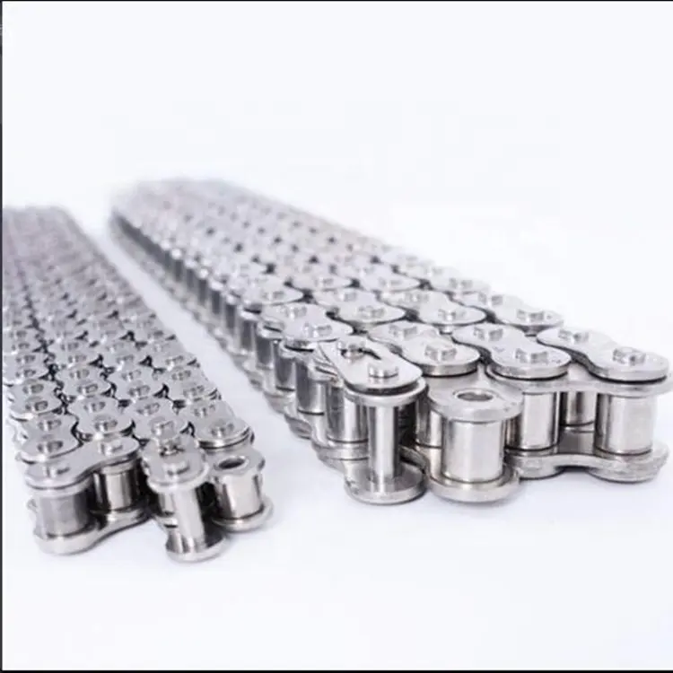
How does the pitch size of a transmission chain affect its performance?
The pitch size of a transmission chain plays a crucial role in determining its performance and suitability for specific applications. The pitch size refers to the distance between adjacent chain links, typically measured from the center of one pin to the center of the next pin.
The pitch size of a transmission chain affects its performance in the following ways:
- Load Capacity: Chains with larger pitch sizes generally have higher load capacities. A larger pitch size allows for larger components, such as pins and rollers, which can withstand higher forces and transmit more power.
- Speed Capability: The pitch size also affects the chain’s speed capability. Chains with smaller pitch sizes are typically designed for higher speeds, as they offer smoother engagement with the sprockets and reduced inertia.
- Wear and Fatigue Resistance: Smaller pitch sizes distribute the load over more contact points, reducing the stress on individual components. This can improve wear resistance and increase the chain’s fatigue life.
- Compactness and Space Limitations: In applications where space is limited, smaller pitch chains are preferred as they allow for a more compact design.
It’s important to note that the selection of the appropriate pitch size depends on the specific application requirements, including the expected load, speed, and available space. Different pitch sizes are available to accommodate a wide range of applications, from light-duty to heavy-duty machinery.
editor by CX 2023-07-18
China high quality Martin Motorcycle Parts Transmission Conveyor Gearbox Short Pitch Precision Roller Chains Bush Chains 10b-19teeth Hub Sprocket near me shop
Product Description
SPROCKET 5/8” X 3/8” 10B Collection SPROCKETS
| For Chain Acc.to DIN8187 ISO/R 606 | |||||
| Tooth Radius r3 | 16.0mm | ||||
| Radius Width C | 1.6mm | ||||
| Tooth Width b1 | 9.0mm | ||||
| Tooth Width B1 | 9.1mm | ||||
| Tooth Width B2 | twenty five.5mm | ||||
| Tooth Width B3 | 42.1mm | ||||
| 10B Sequence ROLLER CHAINS | |||||
| Pitch | 15.875 mm | ||||
| Internal Width | nine.sixty five mm | ||||
| Roller Diameter | ten.16 mm | ||||
| Z | de | dp | SIMPLEX | DUPLEX | TRIPLEX | ||||||
| dm | D1 | A | dm | D2 | A | dm | D3 | A | |||
| 8 | 47. | forty one.forty eight | twenty five | ten | twenty five | 25 | 12 | forty | twenty five | twelve | fifty five |
| 9 | 52.6 | forty six.forty two | thirty | ten | twenty five | thirty | 12 | 40 | 30 | twelve | fifty five |
| ten | fifty seven.five | 51.37 | 35 | ten | twenty five | 35 | 12 | 40 | 35 | 12 | 55 |
| 11 | sixty three. | fifty six.34 | 37 | twelve | 30 | 39 | fourteen | 40 | 39 | sixteen | fifty five |
| 12 | 68. | sixty one.34 | 42 | twelve | 30 | forty four | 14 | 40 | 44 | 16 | fifty five |
| thirteen | seventy three. | 66.32 | forty seven | 12 | thirty | forty nine | 14 | 40 | forty nine | sixteen | 55 |
| 14 | 78. | seventy one.34 | fifty two | 12 | 30 | 54 | fourteen | 40 | fifty four | 16 | 55 |
| 15 | 83. | seventy six.36 | 57 | twelve | 30 | fifty nine | 14 | 40 | 59 | sixteen | fifty five |
| 16 | 88. | eighty one.37 | 60 | 12 | 30 | sixty four | sixteen | forty five | 64 | sixteen | sixty |
| seventeen | 93. | 86.39 | 60 | twelve | thirty | 69 | sixteen | 45 | sixty nine | sixteen | sixty |
| 18 | ninety eight.3 | ninety one.42 | 70 | fourteen | 30 | 74 | sixteen | forty five | seventy four | 16 | 60 |
| 19 | 103.three | ninety six.45 | 70 | 14 | thirty | seventy nine | sixteen | 45 | seventy nine | sixteen | sixty |
| 20 | 108.four | 101.forty nine | 75 | fourteen | 30 | eighty four | sixteen | forty five | 84 | 16 | 60 |
| 21 | 113.four | 106.fifty two | seventy five | 16 | thirty | eighty five | sixteen | 45 | 85 | twenty | sixty |
| 22 | 118. | 111.fifty five | 80 | 16 | 30 | ninety | 16 | 45 | ninety | twenty | sixty |
| 23 | 123.5 | 116.58 | eighty | sixteen | thirty | ninety five | sixteen | forty five | 95 | 20 | 60 |
| 24 | 128.three | 121.sixty two | eighty | sixteen | 30 | a hundred | 16 | forty five | 100 | 20 | sixty |
| 25 | 134. | 126.sixty six | 80 | 16 | 30 | 105 | sixteen | forty five | 105 | twenty | sixty |
| 26 | 139. | 131.70 | eighty five | 20 | 35 | one hundred ten | 20 | forty five | one hundred ten | 20 | sixty |
| 27 | one hundred forty four. | 136.seventy five | eighty five | twenty | 35 | one hundred ten | 20 | forty five | one hundred ten | 20 | sixty |
| 28 | 148.seven | 141.78 | 90 | twenty | 35 | one hundred fifteen | twenty | forty five | a hundred and fifteen | 20 | sixty |
| 29 | 153.8 | 146.eighty three | 90 | 20 | 35 | one hundred fifteen | 20 | forty five | a hundred and fifteen | 20 | 60 |
| 30 | 158.8 | 151.87 | ninety | twenty | 35 | a hundred and twenty | 20 | 45 | a hundred and twenty | twenty | 60 |
| 31 | 163.nine | 156.ninety two | 95 | 20 | 35 | one hundred twenty | 20 | forty five | a hundred and twenty | 20 | sixty |
| 32 | 168.9 | 161.95 | 95 | twenty | 35 | 120 | twenty | forty five | a hundred and twenty | twenty | sixty |
| 33 | 174.5 | 167.00 | ninety five | 20 | 35 | one hundred twenty | twenty | 45 | a hundred and twenty | 20 | sixty |
| 34 | 179. | 172.05 | 95 | twenty | 35 | a hundred and twenty | 20 | forty five | a hundred and twenty | twenty | sixty |
| 35 | 184.1 | 177.10 | 95 | 20 | 35 | a hundred and twenty | twenty | forty five | one hundred twenty | twenty | 60 |
| 36 | 189.one | 182.fifteen | one hundred | twenty | 35 | a hundred and twenty | 20 | 45 | a hundred and twenty | 25 | 60 |
| 37 | 194.2 | 187.twenty | one hundred | twenty | 35 | 120 | 20 | forty five | one hundred twenty | twenty five | sixty |
| 38 | 199.2 | 192.24 | one hundred | 20 | 35 | one hundred twenty | twenty | 45 | 120 | twenty five | 60 |
| 39 | 204.2 | 197.29 | a hundred | 20 | 35 | one hundred twenty | 20 | 45 | one hundred twenty | 25 | 60 |
| 40 | 209.three | 202.34 | a hundred | 20 | 35 | a hundred and twenty | 20 | 45 | 120 | 25 | 60 |
| forty one | 214.eight | 207.38 | *a hundred | 20 | 40 | 120 | 20 | 50 | *130 | 25 | 60 |
| forty two | 2,199 | 212.forty three | *one hundred | 20 | forty | a hundred and twenty | 20 | 50 | *130 | twenty five | 60 |
| 43 | 224.nine | 217.48 | *one hundred | 20 | 40 | a hundred and twenty | 20 | fifty | *one hundred thirty | 25 | sixty |
| 44 | 230. | 222.fifty three | *a hundred | 20 | forty | one hundred twenty | twenty | fifty | *130 | 25 | 60 |
| forty five | 235. | 227.58 | *one hundred | 20 | forty | *one hundred twenty | twenty | 50 | *130 | twenty five | sixty |
| forty six | 240.1 | 232.sixty three | *100 | 20 | 40 | *120 | 20 | 50 | *a hundred thirty | twenty five | sixty |
| 47 | 245.1 | 237.sixty eight | *one hundred | twenty | 40 | *120 | twenty | fifty | *one hundred thirty | twenty five | sixty |
| 48 | 250.2 | 242.73 | *100 | twenty | forty | *one hundred twenty | 20 | 50 | *one hundred thirty | 25 | sixty |
| 49 | 255.two | 247.78 | *100 | 20 | 40 | *120 | 20 | 50 | *130 | twenty five | sixty |
| fifty | 260.3 | 252.eighty two | *a hundred | 20 | forty | *one hundred twenty | 20 | 50 | *a hundred thirty | 25 | sixty |
| 51 | 265.3 | 257.87 | *a hundred | 20 | 40 | *a hundred and twenty | twenty | fifty | *one hundred thirty | 25 | sixty |
| fifty two | 270.four | 262.ninety two | *a hundred | twenty | forty | *120 | 20 | fifty | *one hundred thirty | twenty five | sixty |
| fifty three | 275.4 | 267.97 | *a hundred | twenty | forty | *120 | twenty | fifty | *one hundred thirty | twenty five | sixty |
| 54 | 280.five | 273.03 | *a hundred | twenty | 40 | *a hundred and twenty | twenty | fifty | *a hundred thirty | 25 | 60 |
| fifty five | 285.5 | 278.08 | *a hundred | twenty | 40 | *a hundred and twenty | 20 | fifty | *one hundred thirty | twenty five | sixty |
| fifty six | 290.6 | 283.13 | *a hundred | twenty | 40 | *a hundred and twenty | 20 | 50 | *130 | twenty five | sixty |
| fifty seven | 296. | 288.18 | *100 | 20 | 40 | *a hundred and twenty | twenty | 50 | *130 | twenty five | sixty |
| 58 | three hundred.7 | 293.23 | *a hundred | twenty | forty three | *one hundred twenty | twenty | fifty seven | *one hundred thirty | twenty five | 64 |
| 59 | 305.seven | 298.28 | *one hundred | twenty | forty three | *a hundred and twenty | twenty | 57 | *a hundred thirty | 25 | sixty four |
| sixty | 310.8 | 303.33 | *100 | 20 | forty three | *120 | 20 | 57 | *a hundred thirty | twenty five | 64 |
| 62 | 321.4 | 313.forty three | *100 | 20 | 43 | *one hundred twenty | twenty | 57 | *a hundred thirty | 25 | sixty four |
| 64 | 331.five | 323.53 | *100 | 20 | 43 | *120 | twenty | 57 | *a hundred thirty | 25 | sixty seven |
| sixty five | 336.five | 328.fifty eight | *a hundred | 20 | 43 | *a hundred and twenty | 20 | 57 | *a hundred thirty | twenty five | sixty seven |
| 66 | 341.6 | 333.sixty four | *one hundred | twenty | forty three | *120 | 20 | fifty seven | *a hundred thirty | twenty five | 67 |
| 68 | 351.7 | 343.74 | *one hundred | 20 | 43 | *a hundred and twenty | twenty | 57 | *a hundred thirty | 25 | 67 |
| 70 | 361.eight | 353.84 | *a hundred | 20 | 43 | *one hundred twenty | 20 | 57 | *130 | 25 | sixty seven |
| seventy two | 371.9 | 363.94 | *one hundred | 20 | forty three | *a hundred and twenty | twenty | fifty seven | *a hundred thirty | 25 | sixty seven |
| 75 | 387.one | 379.ten | *one hundred | twenty | forty three | *a hundred and twenty | 20 | fifty seven | *130 | 25 | sixty seven |
| seventy six | 392.1 | 384.15 | *a hundred | twenty | forty three | *120 | twenty | fifty seven | *a hundred thirty | 25 | 67 |
| 78 | 402.2 | 394.twenty five | *a hundred | 20 | forty three | *120 | twenty | 57 | *a hundred thirty | twenty five | sixty seven |
| eighty | 412.3 | 404.36 | *a hundred | twenty | 43 | *130 | 20 | fifty seven | *a hundred thirty | twenty five | 67 |
| 85 | 437.six | 429.62 | *a hundred | 20 | 50 | *one hundred thirty | twenty | 58 | *a hundred thirty | twenty five | 67 |
| 90 | 462.eight | 454.88 | *a hundred | 20 | 50 | *one hundred thirty | 20 | fifty eight | *one hundred thirty | 25 | 67 |
| 95 | 488.five | 480.14 | *one hundred | 20 | fifty | *one hundred thirty | 20 | fifty eight | *130 | twenty five | 67 |
| 100 | 513.four | 505.forty | *a hundred | twenty | fifty | *one hundred thirty | twenty | 58 | *one hundred thirty | twenty five | sixty seven |
| a hundred and ten | 563.nine | 555.ninety two | *100 | twenty | fifty | *a hundred thirty | twenty | 58 | *one hundred thirty | twenty five | 67 |
| 114 | 584.one | 576.13 | *one hundred | 20 | 50 | *a hundred thirty | twenty | fifty eight | *one hundred thirty | 25 | 67 |
| one hundred twenty | 614.four | 606.forty five | *100 | 20 | 50 | *a hundred thirty | 20 | fifty eight | *one hundred thirty | 25 | sixty seven |
| 125 | 639.7 | 631.fifty one | *100 | twenty | fifty | *a hundred thirty | twenty | fifty eight | *a hundred thirty | twenty five | sixty seven |
Notice: *welding hub
Standard Details.
| Product name | DIN ISO Common Sprocket for Roller Chain |
| Materials Available | 1. Stainless Steel: SS304, SS316, and many others |
| two. Alloy Metal: C45, 45Mn, 42CrMo, 20CrMo, and so on | |
| three. OEM according to your request | |
| Area Treatment method | Heat therapy, Quenching treatment method, High frequency normalizing treatment, Polishing, Electrophoresis paint processing, Anodic oxidation remedy, and so forth |
| Characteristic | Fire Resistant, Oil Resistant, Heat Resistant, CZPT resistance, Oxidative resistance, Corrosion resistance, and so on |
| Style criterion | ISO DIN ANSI & Consumer Drawings |
| Dimensions | Buyer Drawings & ISO standard |
| Application | Industrial transmission equipment |
| Bundle | Wood Circumstance / Container and pallet, or manufactured-to-buy |
| Certificate | ISO9001: 2008 |
| Benefit | Top quality very first, Service very first, Aggressive cost, Quickly supply |
| Delivery Time | twenty times for samples. 45 times for official order. |
Installation AND Utilizing
The chain spoket, as a generate or deflection for chains, has pockets to maintain the chain backlinks with a D-profile CZPT area with flat side surfaces parallel to the centre airplane of the chain hyperlinks, and outer surfaces at appropriate angles to the chain hyperlink centre aircraft. The chain backlinks are pressed firmly against the outer surfaces and each and every of the facet surfaces by the angled laying surfaces at the base of the pockets, and also the help surfaces of the wheel physique jointly with the end sides of the webs formed by the top and trailing partitions of the pocket.
Recognize
When CZPT new chainwheels it is quite essential that a new chain is fitted at the identical time, and vice versa. Utilizing an aged chain with new sprockets, or a new chain with aged sprockets will trigger quick put on.
It is essential if you are installing the chainwheels by yourself to have the factory services manual specific to your model. Our chainwheels are manufactured to be a direct CZPT for your OEM chainwheels and as these kinds of, the installation should be carried out according to your models service guide.
For the duration of use a chain will stretch (i.e. the pins will wear causing extension of the chain). Utilizing a chain which has been stretched much more than the previously mentioned greatest allowance causes the chain to trip up the tooth of the sprocket. This brings about damage to the tips of the chainwheels teeth, as the force transmitted by the chain is transmitted fully by means of the leading of the tooth, instead than the entire tooth. This outcomes in serious putting on of the chainwheel.
FOR CHAIN STHangZhouRDS
Requirements businesses (this sort of as ANSI and ISO) sustain specifications for layout, proportions, and interchangeability of transmission chains. For example, the pursuing Table shows data from ANSI regular B29.1-2011 (Precision Power Transmission Roller Chains, Attachments, and Sprockets) designed by the American Modern society of Mechanical Engineers (ASME). See the references[8][9][ten] for additional information.
ASME/ANSI B29.1-2011 Roller Chain Regular SizesSizePitchMaximum Roller DiameterMinimum Final Tensile StrengthMeasuring Load25
| ASME/ANSI B29.1-2011 Roller Chain Normal Measurements | ||||
| Measurement | Pitch | Highest Roller Diameter | Bare minimum Supreme Tensile Strength | Measuring Load |
|---|---|---|---|---|
| twenty five | .250 in (6.35 mm) | .one hundred thirty in (3.30 mm) | 780 lb (350 kg) | 18 lb (8.2 kg) |
| 35 | .375 in (9.53 mm) | .two hundred in (5.08 mm) | 1,760 lb (800 kg) | 18 lb (8.2 kg) |
| 41 | .five hundred in (twelve.70 mm) | .306 in (7.77 mm) | 1,500 lb (680 kg) | 18 lb (8.2 kg) |
| 40 | .500 in (twelve.70 mm) | .312 in (7.92 mm) | 3,one hundred twenty five lb (1,417 kg) | 31 lb (14 kg) |
| fifty | .625 in (15.88 mm) | .400 in (10.16 mm) | four,880 lb (2,210 kg) | forty nine lb (22 kg) |
| 60 | .750 in (19.05 mm) | .469 in (eleven.ninety one mm) | seven,030 lb (3,one hundred ninety kg) | 70 lb (32 kg) |
| 80 | one.000 in (25.forty mm) | .625 in (fifteen.88 mm) | twelve,five hundred lb (5,seven hundred kg) | 125 lb (57 kg) |
| a hundred | one.250 in (31.seventy five mm) | .750 in (19.05 mm) | 19,531 lb (8,859 kg) | 195 lb (88 kg) |
| a hundred and twenty | 1.five hundred in (38.10 mm) | .875 in (22.23 mm) | 28,a hundred twenty five lb (twelve,757 kg) | 281 lb (127 kg) |
| 140 | one.750 in (44.forty five mm) | 1.000 in (25.forty mm) | 38,280 lb (seventeen,360 kg) | 383 lb (174 kg) |
| one hundred sixty | 2.000 in (fifty.80 mm) | one.one hundred twenty five in (28.fifty eight mm) | fifty,000 lb (23,000 kg) | 500 lb (230 kg) |
| a hundred and eighty | two.250 in (57.15 mm) | 1.460 in (37.08 mm) | sixty three,280 lb (28,700 kg) | 633 lb (287 kg) |
| two hundred | 2.five hundred in (sixty three.fifty mm) | one.562 in (39.sixty seven mm) | seventy eight,one hundred seventy five lb (35,460 kg) | 781 lb (354 kg) |
| 240 | three.000 in (76.twenty mm) | one.875 in (forty seven.63 mm) | 112,five hundred lb (51,000 kg) | one,000 lb (450 kg |
For mnemonic needs, under is an additional presentation of key dimensions from the same normal, expressed in fractions of an inch (which was element of the contemplating powering the decision of desired numbers in the ANSI normal):
| Pitch (inches) | Pitch expressed in eighths |
ANSI regular chain quantity |
Width (inches) |
|---|---|---|---|
| 1⁄4 | 2⁄eight | 2five | 1⁄8 |
| 3⁄8 | 3⁄eight | three5 | 3⁄sixteen |
| one⁄two | four⁄eight | four1 | one⁄4 |
| one⁄2 | 4⁄8 | four | 5⁄sixteen |
| five⁄8 | 5⁄8 | five | 3⁄8 |
| 3⁄four | six⁄8 | 6 | one⁄2 |
| one | 8⁄eight | 8 | five⁄eight |
Notes:
one. The pitch is the length between roller facilities. The width is the length in between the url plates (i.e. a bit more than the roller width to allow for clearance).
two. The appropriate-hand digit of the regular denotes 0 = regular chain, 1 = light-weight chain, 5 = rollerless bushing chain.
three. The left-hand digit denotes the number of eighths of an inch that make up the pitch.
four. An “H” adhering to the normal number denotes heavyweight chain. A hyphenated amount pursuing the regular quantity denotes double-strand (2), triple-strand (3), and so on. Thus 60H-3 denotes variety 60 heavyweight triple-strand chain.
A standard bicycle chain (for derailleur gears) utilizes slender 1⁄2-inch-pitch chain. The width of the chain is variable, and does not affect the load ability. The a lot more sprockets at the rear wheel (historically 3-6, presently 7-twelve sprockets), the narrower the chain. Chains are sold according to the number of speeds they are made to perform with, for illustration, “10 speed chain”. Hub gear or solitary pace bicycles use 1/2″ x 1/8″ chains, the place 1/8″ refers to the maximum thickness of a sprocket that can be used with the chain.
Typically chains with parallel formed links have an even amount of links, with each and every slender hyperlink followed by a broad 1.Chains created up with a uniform sort of website link, slim at 1 and broad at the other stop, can be made with an odd variety of hyperlinks, which can be an gain to adapt to a special chainwheel-length on the other side these kinds of a chain tends to be not so robust.
Roller chains produced making use of ISO standard are occasionally referred to as as isochains.
WHY Decide on US
one. Trustworthy High quality Assurance Technique
two. Slicing-Edge Pc-Managed CNC Equipment
three. Bespoke Options from Highly Skilled Specialists
4. Customization and OEM Offered for Particular Software
5. Comprehensive Stock of Spare Elements and Accessories
six. Effectively-Designed Globally Marketing Community
7. Effective Right after-Sale Services Technique
The 219 sets of innovative computerized generation products offer ensures for high solution quality. The 167 engineers and technicians with senior professional titles can design and style and develop merchandise to meet the precise demands of clients, and OEM customizations are also available with us. Our audio global support network can offer clients with well timed soon after-sales technical services.
We are not just a manufacturer and provider, but also an industry consultant. We operate professional-actively with you to provide specialist advice and solution recommendations in purchase to end up with a most expense efficient product offered for your certain application. The clients we provide globally assortment from stop end users to distributors and OEMs. Our OEM replacements can be substituted anywhere needed and ideal for equally fix and new assemblies.
Roller sprockets are commonly used in industrial and professional programs to transmit drive to the chain by meshing with rollers on the chain, the enamel of which mate with the inner plates of the chain. A wide selection of purposes gain from these, such as conveyor belts, big industrial drives, robotics, electrical assembly, and much more.
Ep prefabricated metal sprockets are produced of C1045 metal, induction hardened or warmth-handled metal, four hundred – five hundred BHN hardness. You should specify the resources you want. Unless in any other case asked for, the outdoors diameter of the hub need to be sufficient to accommodate the essential holes and keyways. Keys to these products are not equipped unless requested or installed on the shaft. Split sprockets for welding or break up sprockets for bolts give an inexpensive way to set up sprockets on shafts in which removing of the shaft assembly is prohibited. A lot of dimensions of sprockets are geared up with holes, keyways, and set screws. Discs or partially concluded sprockets are also stocked. For long sprockets and idlers, specify the chain size utilised.

China wholesaler Short Pitch Precision Roller Chains and Bush Chains 10b 35 Teeth Hub Sprocket with Great quality
Product Description
SPROCKET 5/8” X 3/8” 10B Sequence SPROCKETS
| For Chain Acc.to DIN8187 ISO/R 606 | |||||
| Tooth Radius r3 | 16.0mm | ||||
| Radius Width C | 1.6mm | ||||
| Tooth Width b1 | 9.0mm | ||||
| Tooth Width B1 | 9.1mm | ||||
| Tooth Width B2 | twenty five.5mm | ||||
| Tooth Width B3 | 42.1mm | ||||
| 10B Series ROLLER CHAINS | |||||
| Pitch | 15.875 mm | ||||
| Internal Width | 9.sixty five mm | ||||
| Roller Diameter | ten.16 mm | ||||
| Z | de | dp | SIMPLEX | DUPLEX | TRIPLEX | ||||||
| dm | D1 | A | dm | D2 | A | dm | D3 | A | |||
| 8 | forty seven. | forty one.forty eight | 25 | ten | twenty five | 25 | twelve | 40 | twenty five | twelve | fifty five |
| 9 | fifty two.6 | 46.42 | 30 | ten | 25 | thirty | 12 | 40 | 30 | 12 | fifty five |
| 10 | fifty seven.5 | fifty one.37 | 35 | ten | 25 | 35 | twelve | 40 | 35 | twelve | fifty five |
| 11 | sixty three. | 56.34 | 37 | twelve | thirty | 39 | fourteen | forty | 39 | 16 | 55 |
| 12 | 68. | sixty one.34 | 42 | twelve | thirty | forty four | fourteen | forty | forty four | sixteen | fifty five |
| thirteen | seventy three. | sixty six.32 | 47 | 12 | 30 | 49 | fourteen | forty | 49 | 16 | 55 |
| fourteen | seventy eight. | seventy one.34 | 52 | twelve | 30 | fifty four | 14 | forty | fifty four | sixteen | 55 |
| fifteen | eighty three. | 76.36 | fifty seven | twelve | 30 | 59 | fourteen | forty | 59 | sixteen | 55 |
| 16 | 88. | eighty one.37 | sixty | 12 | thirty | 64 | 16 | forty five | sixty four | 16 | sixty |
| 17 | ninety three. | 86.39 | sixty | twelve | thirty | 69 | 16 | forty five | sixty nine | 16 | 60 |
| 18 | 98.three | 91.forty two | 70 | fourteen | thirty | 74 | 16 | 45 | 74 | sixteen | 60 |
| 19 | 103.three | ninety six.45 | 70 | fourteen | 30 | 79 | 16 | forty five | seventy nine | 16 | sixty |
| 20 | 108.4 | one hundred and one.forty nine | seventy five | 14 | 30 | 84 | 16 | forty five | 84 | sixteen | sixty |
| 21 | 113.four | 106.52 | 75 | sixteen | thirty | 85 | 16 | forty five | eighty five | 20 | sixty |
| 22 | 118. | 111.fifty five | eighty | sixteen | 30 | ninety | sixteen | 45 | 90 | 20 | sixty |
| 23 | 123.five | 116.58 | eighty | sixteen | thirty | 95 | 16 | 45 | 95 | 20 | 60 |
| 24 | 128.3 | 121.sixty two | 80 | 16 | 30 | one hundred | 16 | 45 | a hundred | twenty | sixty |
| 25 | 134. | 126.sixty six | eighty | 16 | thirty | one zero five | 16 | forty five | 105 | twenty | 60 |
| 26 | 139. | 131.70 | 85 | twenty | 35 | one hundred ten | twenty | 45 | a hundred and ten | twenty | sixty |
| 27 | a hundred and forty four. | 136.75 | eighty five | 20 | 35 | a hundred and ten | 20 | forty five | one hundred ten | twenty | 60 |
| 28 | 148.seven | 141.78 | 90 | twenty | 35 | a hundred and fifteen | twenty | forty five | one hundred fifteen | 20 | 60 |
| 29 | 153.8 | 146.eighty three | 90 | 20 | 35 | 115 | twenty | 45 | one hundred fifteen | 20 | 60 |
| thirty | 158.eight | 151.87 | 90 | twenty | 35 | one hundred twenty | twenty | forty five | a hundred and twenty | 20 | sixty |
| 31 | 163.nine | 156.92 | ninety five | 20 | 35 | one hundred twenty | twenty | 45 | a hundred and twenty | twenty | 60 |
| 32 | 168.9 | 161.ninety five | 95 | twenty | 35 | one hundred twenty | 20 | 45 | 120 | 20 | 60 |
| 33 | 174.five | 167.00 | 95 | twenty | 35 | 120 | twenty | 45 | 120 | 20 | sixty |
| 34 | 179. | 172.05 | ninety five | twenty | 35 | a hundred and twenty | 20 | forty five | one hundred twenty | 20 | 60 |
| 35 | 184.one | 177.ten | ninety five | 20 | 35 | one hundred twenty | 20 | forty five | a hundred and twenty | 20 | sixty |
| 36 | 189.1 | 182.15 | 100 | twenty | 35 | 120 | twenty | forty five | a hundred and twenty | twenty five | sixty |
| 37 | 194.2 | 187.20 | one hundred | 20 | 35 | 120 | 20 | 45 | 120 | 25 | 60 |
| 38 | 199.2 | 192.24 | one hundred | twenty | 35 | a hundred and twenty | 20 | forty five | a hundred and twenty | 25 | 60 |
| 39 | 204.2 | 197.29 | 100 | 20 | 35 | a hundred and twenty | twenty | 45 | 120 | twenty five | sixty |
| forty | 209.3 | 202.34 | 100 | twenty | 35 | one hundred twenty | 20 | forty five | 120 | twenty five | 60 |
| forty one | 214.8 | 207.38 | *100 | twenty | 40 | 120 | 20 | fifty | *one hundred thirty | 25 | 60 |
| forty two | two,199 | 212.forty three | *100 | twenty | forty | one hundred twenty | 20 | fifty | *130 | twenty five | sixty |
| forty three | 224.9 | 217.forty eight | *a hundred | 20 | forty | a hundred and twenty | 20 | fifty | *130 | twenty five | 60 |
| 44 | 230. | 222.53 | *one hundred | twenty | forty | 120 | twenty | 50 | *130 | 25 | sixty |
| 45 | 235. | 227.fifty eight | *one hundred | twenty | forty | *120 | 20 | fifty | *a hundred thirty | twenty five | sixty |
| 46 | 240.1 | 232.63 | *100 | twenty | forty | *a hundred and twenty | 20 | 50 | *one hundred thirty | 25 | 60 |
| forty seven | 245.1 | 237.68 | *a hundred | 20 | 40 | *one hundred twenty | 20 | 50 | *a hundred thirty | twenty five | 60 |
| 48 | 250.two | 242.seventy three | *100 | twenty | forty | *a hundred and twenty | 20 | 50 | *a hundred thirty | twenty five | 60 |
| 49 | 255.2 | 247.seventy eight | *100 | 20 | forty | *one hundred twenty | twenty | fifty | *130 | 25 | sixty |
| 50 | 260.three | 252.eighty two | *100 | twenty | forty | *a hundred and twenty | twenty | fifty | *130 | twenty five | sixty |
| 51 | 265.three | 257.87 | *100 | 20 | 40 | *a hundred and twenty | twenty | fifty | *one hundred thirty | 25 | 60 |
| 52 | 270.four | 262.92 | *a hundred | twenty | forty | *120 | twenty | 50 | *130 | twenty five | sixty |
| fifty three | 275.four | 267.ninety seven | *a hundred | 20 | forty | *a hundred and twenty | twenty | 50 | *one hundred thirty | 25 | 60 |
| fifty four | 280.five | 273.03 | *100 | twenty | 40 | *a hundred and twenty | 20 | fifty | *130 | 25 | 60 |
| 55 | 285.5 | 278.08 | *one hundred | twenty | forty | *120 | twenty | 50 | *130 | twenty five | 60 |
| 56 | 290.six | 283.thirteen | *100 | twenty | 40 | *120 | twenty | fifty | *130 | twenty five | sixty |
| fifty seven | 296. | 288.eighteen | *one hundred | 20 | forty | *120 | twenty | fifty | *130 | 25 | sixty |
| 58 | 300.seven | 293.23 | *one hundred | 20 | forty three | *120 | twenty | fifty seven | *one hundred thirty | 25 | sixty four |
| 59 | 305.seven | 298.28 | *one hundred | 20 | 43 | *a hundred and twenty | 20 | fifty seven | *130 | 25 | sixty four |
| sixty | 310.eight | 303.33 | *one hundred | 20 | 43 | *one hundred twenty | twenty | 57 | *one hundred thirty | 25 | 64 |
| sixty two | 321.4 | 313.43 | *a hundred | twenty | 43 | *120 | twenty | 57 | *130 | 25 | 64 |
| 64 | 331.five | 323.53 | *a hundred | twenty | forty three | *a hundred and twenty | 20 | 57 | *130 | twenty five | sixty seven |
| sixty five | 336.5 | 328.58 | *one hundred | 20 | 43 | *one hundred twenty | twenty | fifty seven | *130 | twenty five | 67 |
| 66 | 341.6 | 333.sixty four | *a hundred | twenty | forty three | *one hundred twenty | twenty | 57 | *130 | 25 | sixty seven |
| sixty eight | 351.7 | 343.seventy four | *100 | 20 | forty three | *one hundred twenty | twenty | fifty seven | *a hundred thirty | 25 | sixty seven |
| 70 | 361.8 | 353.84 | *a hundred | twenty | forty three | *one hundred twenty | 20 | 57 | *a hundred thirty | twenty five | 67 |
| seventy two | 371.9 | 363.ninety four | *100 | 20 | forty three | *120 | twenty | 57 | *a hundred thirty | twenty five | sixty seven |
| 75 | 387.1 | 379.10 | *one hundred | twenty | 43 | *one hundred twenty | 20 | 57 | *130 | twenty five | 67 |
| seventy six | 392.1 | 384.fifteen | *one hundred | twenty | forty three | *a hundred and twenty | twenty | fifty seven | *one hundred thirty | twenty five | sixty seven |
| seventy eight | 402.two | 394.twenty five | *100 | 20 | forty three | *a hundred and twenty | 20 | 57 | *one hundred thirty | 25 | sixty seven |
| 80 | 412.three | 404.36 | *one hundred | twenty | 43 | *a hundred thirty | twenty | 57 | *a hundred thirty | twenty five | 67 |
| eighty five | 437.six | 429.sixty two | *one hundred | 20 | fifty | *one hundred thirty | twenty | 58 | *a hundred thirty | 25 | 67 |
| 90 | 462.eight | 454.88 | *100 | twenty | 50 | *a hundred thirty | twenty | 58 | *a hundred thirty | twenty five | 67 |
| 95 | 488.five | 480.fourteen | *a hundred | 20 | 50 | *one hundred thirty | 20 | fifty eight | *a hundred thirty | twenty five | sixty seven |
| 100 | 513.4 | 505.40 | *one hundred | twenty | 50 | *one hundred thirty | 20 | fifty eight | *one hundred thirty | twenty five | 67 |
| 110 | 563.nine | 555.ninety two | *a hundred | twenty | 50 | *a hundred thirty | twenty | fifty eight | *a hundred thirty | 25 | 67 |
| 114 | 584.one | 576.thirteen | *one hundred | twenty | fifty | *130 | 20 | fifty eight | *a hundred thirty | twenty five | 67 |
| one hundred twenty | 614.four | 606.forty five | *a hundred | twenty | 50 | *a hundred thirty | twenty | 58 | *a hundred thirty | 25 | 67 |
| 125 | 639.7 | 631.fifty one | *a hundred | 20 | fifty | *a hundred thirty | twenty | 58 | *130 | 25 | sixty seven |
Observe: *welding hub
Fundamental Information.
| Product name | DIN ISO Regular Sprocket for Roller Chain |
| Materials Available | one. Stainless Steel: SS304, SS316, etc |
| 2. Alloy Steel: C45, 45Mn, 42CrMo, 20CrMo, etc | |
| three. OEM according to your request | |
| Area Treatment | Heat treatment, Quenching treatment method, High frequency normalizing treatment, Sharpening, Electrophoresis paint processing, Anodic oxidation treatment, etc |
| Attribute | Fire Resistant, Oil Resistant, Heat Resistant, CZPT resistance, Oxidative resistance, Corrosion resistance, etc |
| Layout criterion | ISO DIN ANSI & Buyer Drawings |
| Dimensions | Client Drawings & ISO standard |
| Software | Industrial transmission products |
| Bundle | Picket Circumstance / Container and pallet, or made-to-order |
| Certification | ISO9001: 2008 |
| Benefit | Top quality initial, Support very first, Competitive price, Quick delivery |
| Supply Time | twenty days for samples. 45 days for official order. |
Installation AND Utilizing
The chain spoket, as a drive or deflection for chains, has pockets to maintain the chain backlinks with a D-profile CZPT part with flat aspect surfaces parallel to the centre airplane of the chain back links, and outer surfaces at appropriate angles to the chain url centre airplane. The chain back links are pressed firmly from the outer surfaces and every of the side surfaces by the angled laying surfaces at the foundation of the pockets, and also the assist surfaces of the wheel entire body jointly with the finish sides of the webs shaped by the foremost and trailing partitions of the pocket.
Discover
When CZPT new chainwheels it is quite important that a new chain is equipped at the same time, and vice versa. Using an previous chain with new sprockets, or a new chain with previous sprockets will cause fast dress in.
It is important if you are setting up the chainwheels by yourself to have the manufacturing facility provider manual certain to your model. Our chainwheels are created to be a direct CZPT for your OEM chainwheels and as these kinds of, the installation need to be performed in accordance to your designs services manual.
For the duration of use a chain will extend (i.e. the pins will put on causing extension of the chain). Using a chain which has been stretched more than the above greatest allowance causes the chain to journey up the teeth of the sprocket. This triggers damage to the ideas of the chainwheels teeth, as the drive transmitted by the chain is transmitted entirely by means of the prime of the tooth, instead than the total tooth. This final results in severe wearing of the chainwheel.
FOR CHAIN STHangZhouRDS
Expectations businesses (this kind of as ANSI and ISO) preserve requirements for style, dimensions, and interchangeability of transmission chains. For case in point, the pursuing Table demonstrates information from ANSI common B29.1-2011 (Precision Electricity Transmission Roller Chains, Attachments, and Sprockets) developed by the American Modern society of Mechanical Engineers (ASME). See the references[8][9][ten] for further details.
ASME/ANSI B29.1-2011 Roller Chain Regular SizesSizePitchMaximum Roller DiameterMinimum Final Tensile StrengthMeasuring Load25
| ASME/ANSI B29.1-2011 Roller Chain Regular Sizes | ||||
| Measurement | Pitch | Greatest Roller Diameter | Least Supreme Tensile Toughness | Measuring Load |
|---|---|---|---|---|
| twenty five | .250 in (6.35 mm) | .one hundred thirty in (3.30 mm) | 780 lb (350 kg) | 18 lb (8.2 kg) |
| 35 | .375 in (9.53 mm) | .200 in (5.08 mm) | 1,760 lb (800 kg) | 18 lb (8.2 kg) |
| forty one | .500 in (12.70 mm) | .306 in (7.seventy seven mm) | one,five hundred lb (680 kg) | eighteen lb (8.2 kg) |
| 40 | .five hundred in (12.70 mm) | .312 in (7.ninety two mm) | 3,a hundred twenty five lb (1,417 kg) | 31 lb (fourteen kg) |
| fifty | .625 in (fifteen.88 mm) | .four hundred in (10.16 mm) | 4,880 lb (2,210 kg) | forty nine lb (22 kg) |
| sixty | .750 in (19.05 mm) | .469 in (eleven.ninety one mm) | 7,030 lb (3,190 kg) | 70 lb (32 kg) |
| 80 | 1.000 in (25.40 mm) | .625 in (15.88 mm) | 12,five hundred lb (5,seven hundred kg) | a hundred twenty five lb (57 kg) |
| one hundred | one.250 in (31.seventy five mm) | .750 in (19.05 mm) | 19,531 lb (8,859 kg) | 195 lb (88 kg) |
| one hundred twenty | one.five hundred in (38.10 mm) | .875 in (22.23 mm) | 28,125 lb (12,757 kg) | 281 lb (127 kg) |
| one hundred forty | 1.750 in (44.forty five mm) | one.000 in (25.forty mm) | 38,280 lb (17,360 kg) | 383 lb (174 kg) |
| 160 | two.000 in (fifty.eighty mm) | 1.a hundred twenty five in (28.fifty eight mm) | fifty,000 lb (23,000 kg) | five hundred lb (230 kg) |
| 180 | 2.250 in (57.15 mm) | one.460 in (37.08 mm) | 63,280 lb (28,seven-hundred kg) | 633 lb (287 kg) |
| 200 | two.500 in (sixty three.fifty mm) | 1.562 in (39.sixty seven mm) | 78,a hundred seventy five lb (35,460 kg) | 781 lb (354 kg) |
| 240 | three.000 in (76.20 mm) | 1.875 in (forty seven.sixty three mm) | 112,five hundred lb (fifty one,000 kg) | one,000 lb (450 kg |
For mnemonic functions, beneath is one more presentation of crucial proportions from the exact same standard, expressed in fractions of an inch (which was component of the considering behind the choice of desired numbers in the ANSI normal):
| Pitch (inches) | Pitch expressed in eighths |
ANSI regular chain variety |
Width (inches) |
|---|---|---|---|
| 1⁄4 | two⁄8 | twofive | 1⁄8 |
| 3⁄eight | 3⁄8 | three5 | 3⁄16 |
| 1⁄2 | 4⁄8 | 4one | one⁄4 |
| one⁄2 | four⁄eight | four | five⁄sixteen |
| five⁄eight | 5⁄eight | 5 | three⁄8 |
| three⁄four | 6⁄8 | 6 | one⁄two |
| one | eight⁄eight | 8 | 5⁄8 |
Notes:
one. The pitch is the length between roller centers. The width is the length between the url plates (i.e. somewhat more than the roller width to allow for clearance).
two. The appropriate-hand digit of the common denotes 0 = normal chain, 1 = lightweight chain, 5 = rollerless bushing chain.
3. The left-hand digit denotes the amount of eighths of an inch that make up the pitch.
four. An “H” following the common quantity denotes heavyweight chain. A hyphenated quantity following the normal variety denotes double-strand (2), triple-strand (3), and so on. Hence 60H-3 denotes number sixty heavyweight triple-strand chain.
A typical bicycle chain (for derailleur gears) makes use of slender 1⁄2-inch-pitch chain. The width of the chain is variable, and does not affect the load capacity. The far more sprockets at the rear wheel (historically 3-6, presently 7-12 sprockets), the narrower the chain. Chains are bought in accordance to the variety of speeds they are made to function with, for illustration, “10 velocity chain”. Hub equipment or single speed bicycles use 1/2″ x 1/8″ chains, the place 1/8″ refers to the greatest thickness of a sprocket that can be utilized with the chain.
Normally chains with parallel formed backlinks have an even quantity of links, with each slender link adopted by a broad 1.Chains built up with a uniform type of website link, slim at 1 and broad at the other end, can be manufactured with an odd variety of links, which can be an benefit to adapt to a special chainwheel-length on the other aspect these kinds of a chain tends to be not so sturdy.
Roller chains made utilizing ISO common are at times known as as isochains.
WHY Decide on US
1. Reputable Quality Assurance Method
2. Reducing-Edge Pc-Controlled CNC Devices
three. Bespoke Solutions from Extremely Seasoned Experts
four. Customization and OEM Available for Particular Software
five. In depth Inventory of Spare Areas and Accessories
six. Nicely-Produced Throughout the world Marketing Community
seven. Efficient Following-Sale Services Method
The 219 sets of innovative computerized production equipment give guarantees for higher item high quality. The 167 engineers and experts with senior specialist titles can design and style and develop merchandise to fulfill the specific needs of customers, and OEM customizations are also offered with us. Our seem global provider community can give customers with well timed soon after-product sales complex companies.
We are not just a company and supplier, but also an market expert. We operate pro-actively with you to offer you expert suggestions and merchandise recommendations in get to stop up with a most cost successful product accessible for your certain application. The clientele we serve globally range from finish customers to distributors and OEMs. Our OEM replacements can be substituted where ever required and suitable for both mend and new assemblies.
Sprockets are toothed, profiled wheels that mesh with the chain to transmit motion. Our sprockets are personalized fabricated substantial-toughness aluminum, black anodized for exceptional functionality. Flat sprockets include ep patterns and are appropriate with all other parts. Blade Sprockets are 6061-T6 Aluminum Hub Sprockets are 7075-T6 Aluminum Teeth Laser Compatible #25 or #25H Roller Chains Engraved On Each and every Sprocket Now Easy To Use With Our Chain Tube By way of Pipe
Sprockets are produced to ISO606 and ASME B29.100 requirements, obtainable in plate, single and double hub configurations, created from large quality carbon metal, optional tapered bushings simplify installation and removal, treatment options accessible on ask for, which includes black oxide